

kirkie
-
Posts
94 -
Cadastrado em
-
Última visita
-
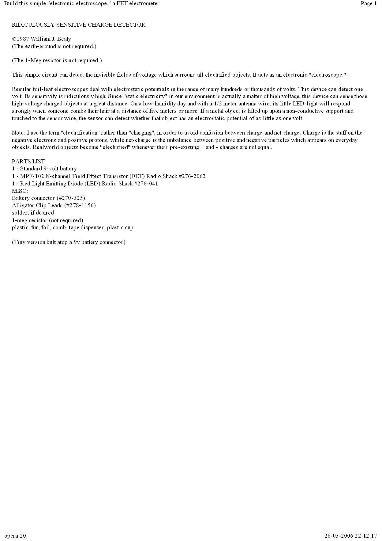
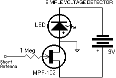
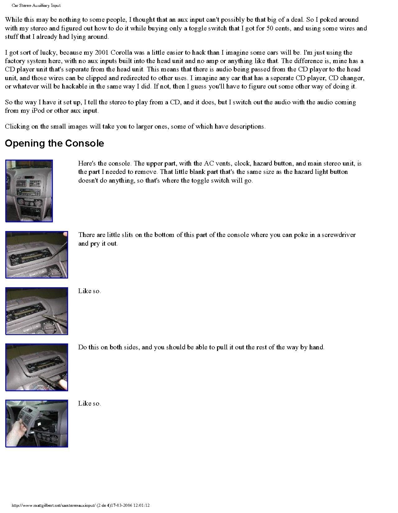
Boas aqui vai um pequeno projecto para detectar eletricidade estatica... CONSTRUCTION HINTS Warning: don't connect the battery until you are SURE you've hooked everything up exactly right. It's possible to burn out the FET or the LED if they are connected incorrectly. Don't let the transistor's wires bump together even briefly, or it will flash the LED and burn it out. NOTE: Don't ever connect any LED directly to a 9-volt battery, it will burn out the LED. Without the transistor to limit the current, a bare LED needs a 1000-ohm resistor wired in series if connected to the 9-volt battery. Warning: Avoid touching the Gate wire of the FET. Any small sparks jumping from your finger to the Gate wire can damage the transistor internally. QUICK INSTRUCTIONS: Use three clipleads. Bend the Gate wire of the FET upwards (see the small diagram above to see which lead is the Gate, or check the diagram on the cardboard of the Radio Shack FET.) The Gate acts as an antenna, so leave it unconnected. Use one cliplead to connect the middle transistor lead to the red positive lead for the 9V battery clip. Connect the remaining transistor lead to the positive lead of the LED (the longer LED lead is usually the positive one.) Connect the LED's remaining lead (the negative one) to the black negative lead for the 9V battery clip. Check all connections twice, then carefully connect the 9V battery to the battery clip. The LED should light up. If the LED remains dark, try lighting it up by waving a charged plastic pen or ruler near the gate lead (charge it by rubbing it on hair.) The 1-meg resistor helps protect the FET from being harmed by any accidental sparks to its Gate lead. The circuit will work fine without this resistor. Just don't intentionally "zap" the Gate fire with a charged object or your charged finger. To test the circuit, charge up a pen or a comb on your hair, then wave it close to the little "antenna" wire. The LED should go dark. When you remove the electrified pen or comb, the LED should light up again. IF IT DOESN'T WORK, the humidity might be too high. Or, your LED might be wired backwards, or the transistor is connected wrong, or maybe your transistor is burned out. Make sure that the transistor is connected similar to the little drawing above. Also, if the polarity of the LED is reversed, the LED will not light up. Try changing the connections to your LED to reverse their order, then connect the battery and test the circuit again. If you suspect that humidity is very high, test this by rubbing a balloon or a plastic object upon your arm. If the balloon does not attract your arm hairs, humidity is too high.

-
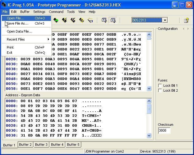
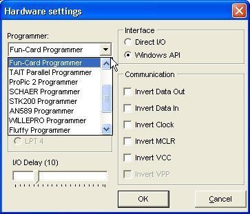
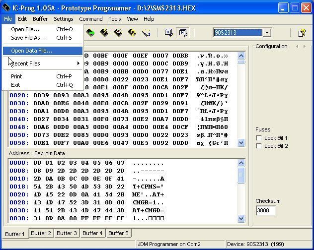
Bom aqui tem um projecto de um gravador de avr de baixo custo ( esse projecto foi me enviado pelo nico Valeu ) Aqui podem fazer o download do icprog http://www.ic-prog.com/index1.htm
-
O raio de rastreio tudo depende se voce tiver um bom receptor...e uma boa antena mas como diz ai no projecto o raio de alcance vai de 3/8 to 1/2 mile( tenha em consideraçao que 1 milha tem cerca de 1600 metros) Quanto a fotos da placa inda não fiz.... mas vou fazer e a ver se depois posto aqui faça uma plaquinha igual a que esta na imagem e lembre-se que quanto mais pequenina melhor... esse projecto é persuposto ficar com um peso de entre 8 a 10 gramas já com pilha... força faça o projecto pegue num receptor de fm porcure o sinal ( ou seja teste qual a freqüência do sinal primeiro antes de isntalar isso no cachorro fugitivo) depois de feedback... que eu tambem tenho um problema identico e vou fazer tambem... força ai! qualquer coisa grite
-
Matheus o que é que não entendeu? ta ai tudo... so que ta em inglês... Isso é um trasmissor de sinal fm bem pequenino do tamanho um pouco maior que uma unha para por tipo na coleira do cao ou isso funciona com pilhas tipo de relogio... que quer que lhe explique mais?
-
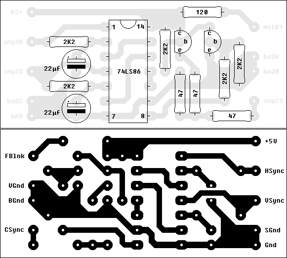
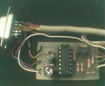
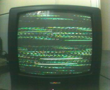
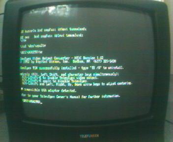
Bom aqui fica um projecto de como converter de vga para a tv.... Connecting your Computer to a Television It is a nasty surprise when you switch your monitor on and nothing appears on screen after a patient wait. Even though the resolution is much low, a television may help you to conduct basic procedures (copying your files for example) in such an emergency. You may think that this is only possible through expensive VGA cards but it's not true. A simple circuit can combine the VGA synchronization signals into composite TV synchronization signal. Following circuit by Tomi Engdahl carries out this job successfully without any problems. It utilizes a TTL IC, two transistors and a few resistors. By putting all of the components on a PCB makes it easier to prepare a portable VGA to TV adapter. You'll need a male VGA connector to be connected to your PC and a Scart connector for your TV. Six lines of cable goes from VGA Card to TV without any alteration, only three of them is needed to be connected to the PCB board. Here is a PCB design I suggest using You'll need VGA connector's and Scart's pinouts also, so here they are. Since circuit does not utilizes high currents, a very thin PCB plate would be enough. After drawing and etching processes, drill the holes and solder the components. Attach wires to the proper connection points and apply +5V supply voltage. If there's nothing wrong, you should measure nearly 75 mA current drag for a 74LS86 low power Schottky TTL type IC and again nearly 100 mA current drag for a 74S86 type IC. Since sweeping frequencies of the VGA boards are higher than the TV's, a software is needed to alter it. Here is one called Television Eyes which both enables you to use circuit in DOS and Microsoft Windows (at 640 x 480 resolution). Just start your PC in DOS mode and run 'te.com' to install it as a TSR. If you press ALT - Left SHIFT - E keys simultaneously, the sweeping frequency of the VGA board will be changed and your TV will be able to sync the signal it receives. Here are screenshots showing the unsynched and synched states of the TV screen displaying DOS. Text mode applications on DOS works pleasant, as long as they are not have details too much. For example good old Norton Commander looks very good on the TV. After switching the Windows to 640 x 480, 16 colors mode (standard VGA) and applying 'te.com' after a reboot, you may be able to view Windows too. File 'winte.exe' enables/disables the frequency alteration and makes it possible to adjust alignment of the screen. Picture quality is worse in Windows that even texts of the icons are unreadable. But as stated earlier, this work is intended to make it possible to use your PC in case of a monitor emergency. To blind-boot your PC in such an emergency condition; prepare a .BAT file with a simple name (for example 't.bat' ) which calls the te.com where it is located. Than you can connect the circuit to your PC and TV, boot the computer in DOS mode, and type 't' then press ALT - Left SHIFT - E to get everything in order.
-
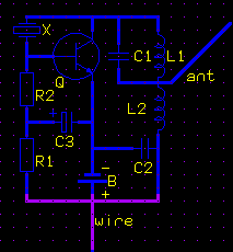
Esse projecto é para se fazer um localizador para animais.... Tracking transmitter taken from the American Institute of Biological Sciences Bioinstrumentation Advisory Council information module M15 prepared by William W. Cochran, 1 December 1967. The transmitter is a pulsed continuos wave (CW) transmitter weighing 8 to 10 grams including the battery. It is only slightly larger than a man's thumb nail. The ground range is 3/8 to 1/2 mile with a good receiver and antenna system. The transmitter is powered by a small watch battery and is good for several months of continuos operation. Parts: X.......Crystal, type FM1. 3rd overtone for 145-160MHz, 5th overtone for 220 MHz Q...... Transistor, Amperex type A415 (original type specified) NTE 107, MPS6507, 2N3904 or most VHF transistors ......... (the transistor used can make a difference so experiment for the best results) R2.... 1500 ohm, 1/8 watt R1.... between 80K and 600K, 1/8 watt. This resistor determines the "beep" rate and is effected ........ by battery voltage and the transistor selected. C1.... Subminiature 15 mmf capacitor C2.... Subminiature .001 mf capacitor C3.... 2mf subminature capacitor ant... 12 inch L1.... 12.5 to 13 turns of #36 enameled wire wound on a 1/8 inch form and removed. L2.... 4.5 turns of #32 enameled wire wound on a 1/8 inch form and removed. wire... wire used to provide capacity to the animal B..... Battery, mercury type, 1.5volt
-
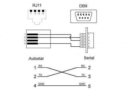
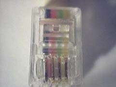
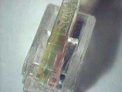
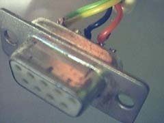
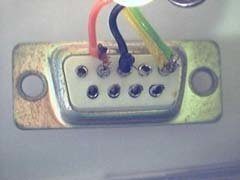
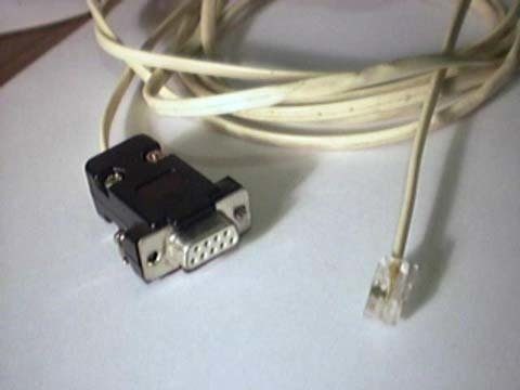
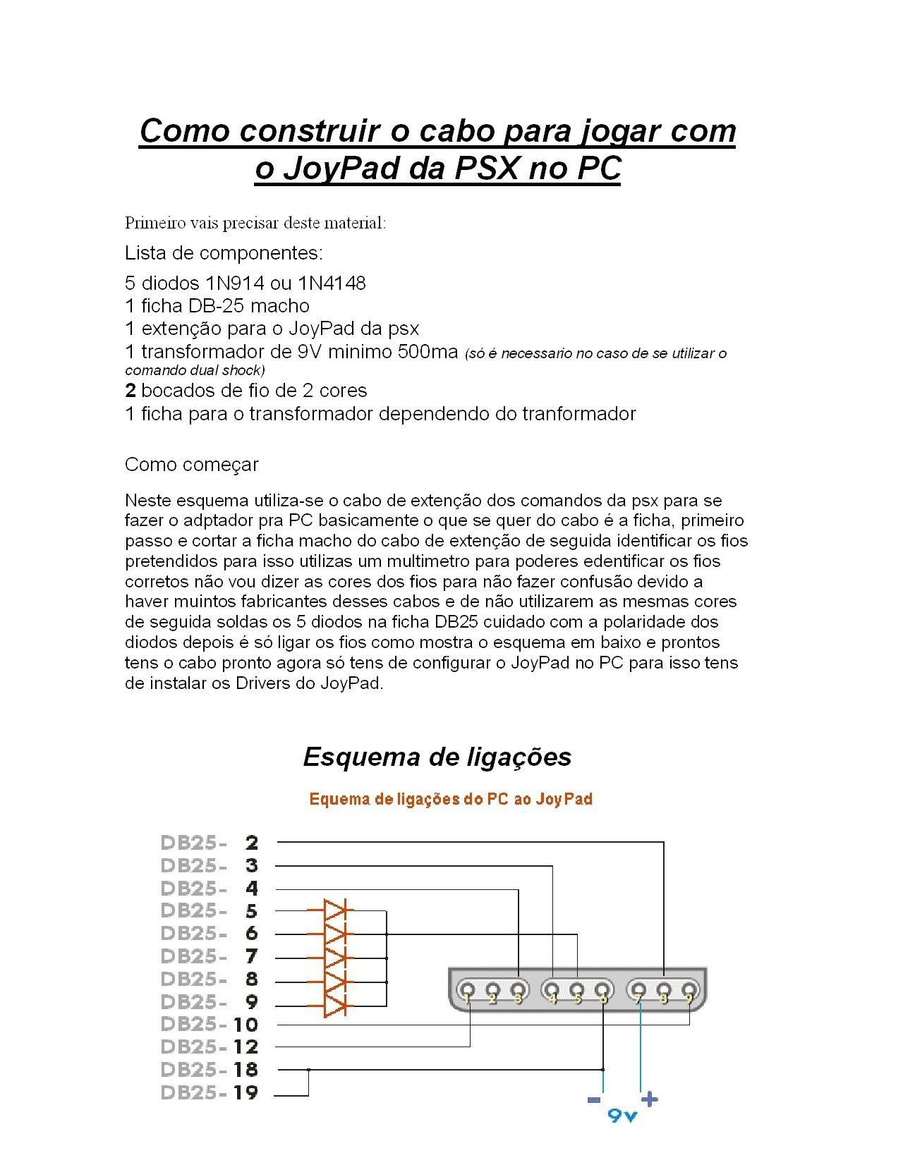
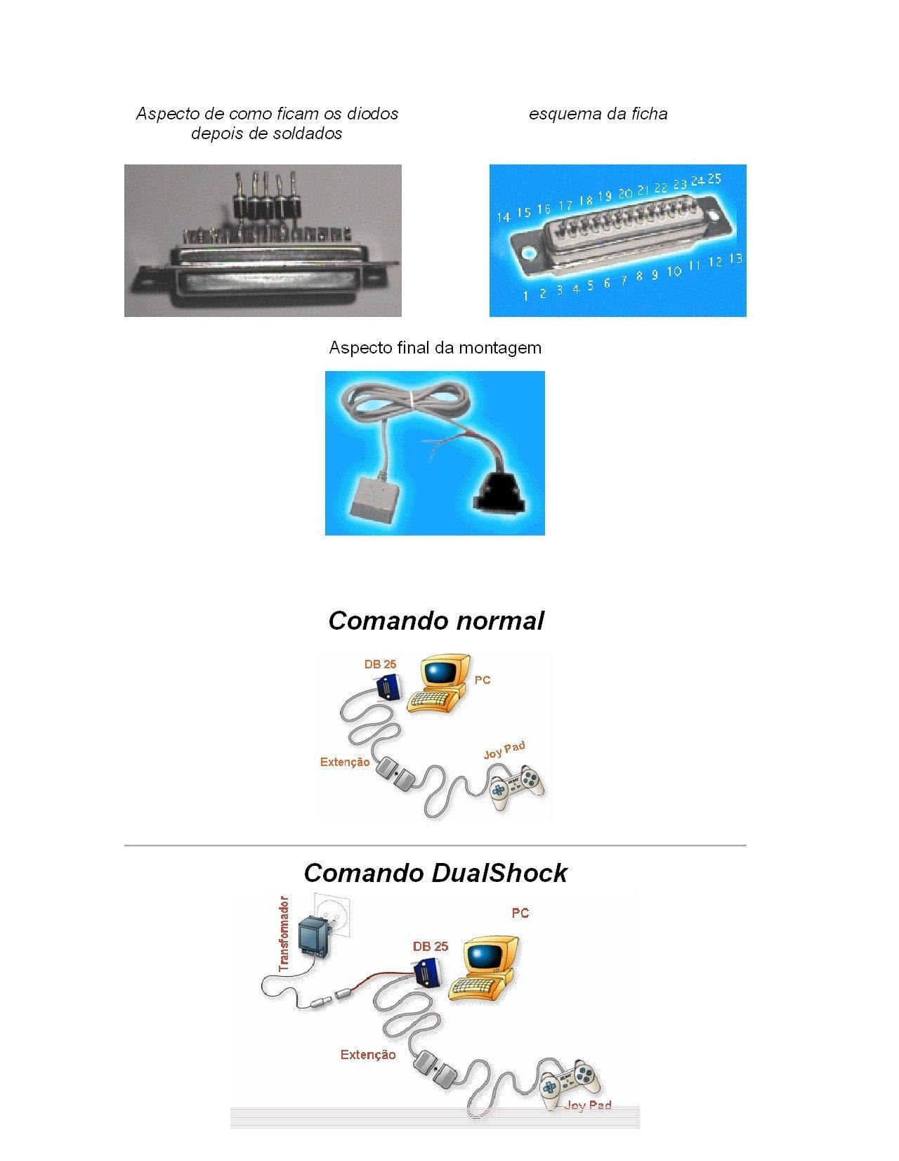
O cabo #505 O cabo de ligação não é algo que se possa adquirir numa loja de informática, pois embora uma das fichas seja standard RS232 de 9 pinos ou de 25 pinos, a outra (a que se liga à porta do autostar) não é tão vulgar, havendo então apenas duas alternativas: Adquirir o cabo #505 que a Meade comercializa, ou da concorrência (Scopetronix) Construir o nosso próprio cabo A primeira opção é de longe a mais segura e a mais cara e proválmente será a mais adequada para quem não tem (ou não quer ter) experiência (pouca) a soldar uns fios. A segunda opção é extremamente barata (até 5x mais barata) e requere algum à vontade a soldar. È um pequeno projecto interessante. A "receita" é a seguinte: 1 cabo com 4 fios condutores coloridos (só são necessários 3). Não deverá exceder os 8,10 metros. 1 ficha RJ9 - para ligar ao autostar. Esta ficha é vulgarmente utilizada em telefones, sendo ligeiramente menos larga do que a ficha de parede. 1 ficha série de 9 pinos fêmea - para ligar ao computador Todos estes componentes encontram-se em qualquer loja de electronica e não deverão custar mais de 1000 escudos. O esquema de ligação é o seguinte: quanto ao software procurem na net consoante o vosso aparelho...
-
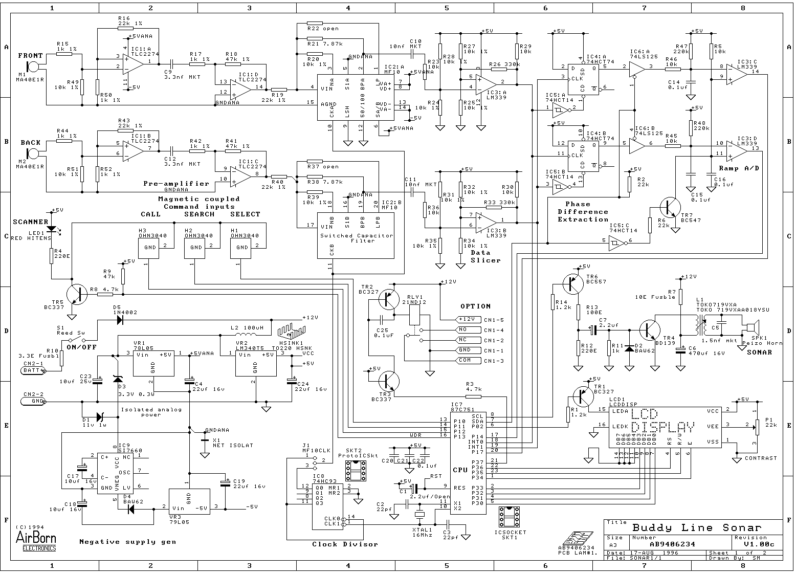
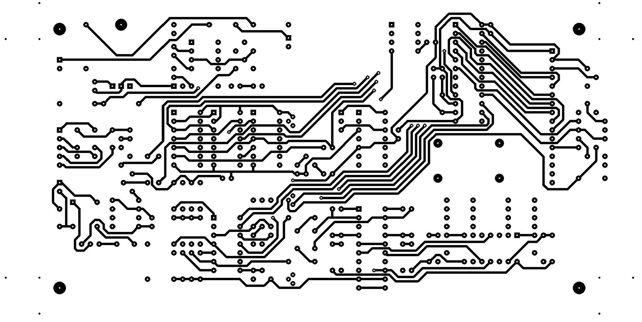
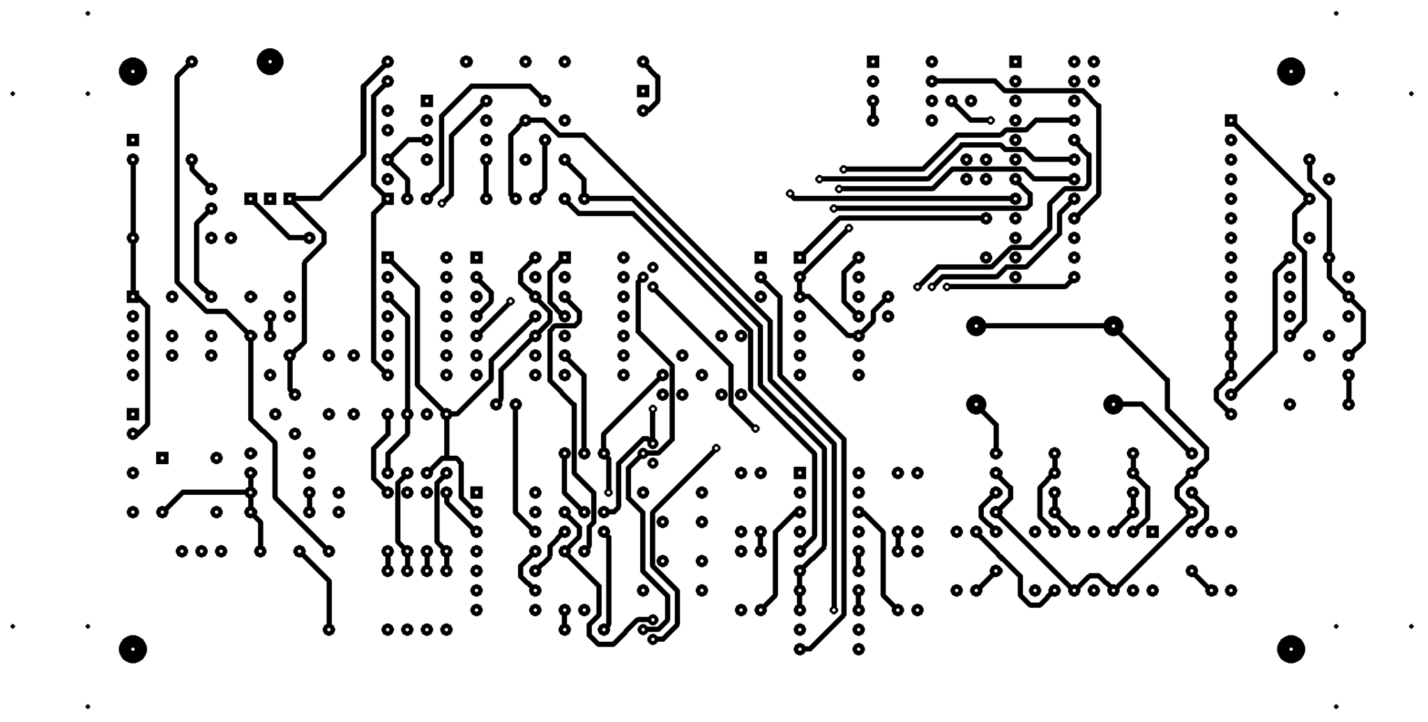
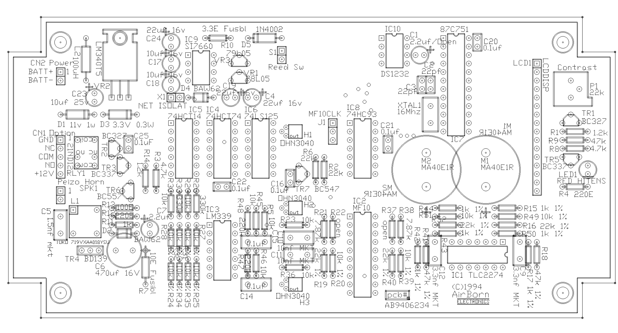
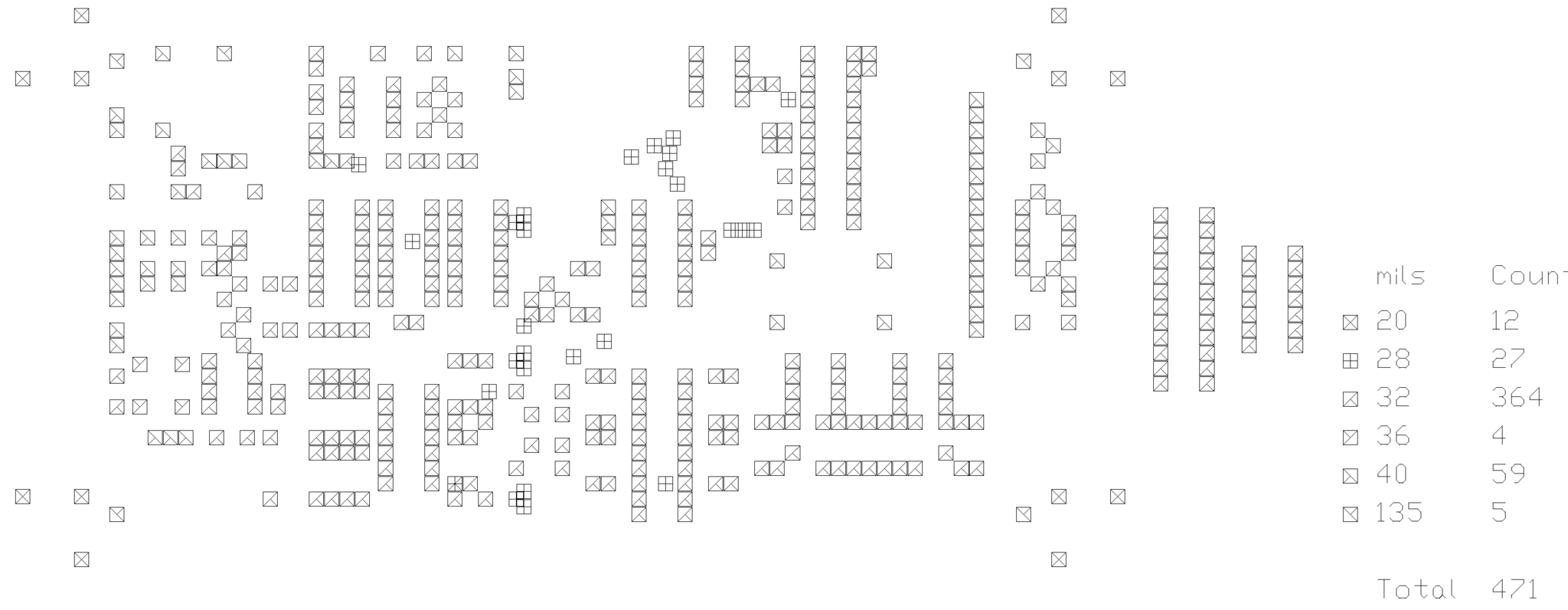
Boas aqui esta um projecto bem interessante mass um bocadinho complexo... Este projecto é para a construçoa de um sonar(sim! esses aparelhinhos para detectar cardume peixes,etc...) Aui esta o esquema Aqui tem a parte de baixo da placa circuito impresso aqui tem a parte de cima da placa de circuito impresso Aqui tem o esquema das furaçoes a fazer Aqui tem a colocaçao dos componentes na placa de circuito impresso Aqui esta a partlist SONAR1.PCB 21:55 8-12-1994 PCB Parts List A1 ©1994 LOGO1 C1 2.2UF/OPEN RB.1/.2 C2 22PF RAD0.1 C3 22PF RAD0.1 C4 22UF 16V RB.1/.2 C19 22UF 16V RB.1/.2 C24 22UF 16V RB.1/.2 C5 1.5NF MKT RAD0.2 C6 470UF 16V RB.2/.4 C7 2.2UF RB.1/.2 C9 3.3NF MKT RAD0.2 C12 3.3NF MKT RAD0.2 C10 10NF MKT RAD0.2 C11 10NF MKT RAD0.2 C14 0.1UF RAD0.2 C15 0.1UF RAD0.2 C16 0.1UF RAD0.1 C20 0.1UF RAD0.1 C21 0.1UF RAD0.1 C22 0.1UF RAD0.1 C25 0.1UF RAD0.1 C17 10UF 16V RB.1/.2 C18 10UF 16V RB.1/.2 C23 10UF 25V RB.1/.2 CN1 OPTION SIP5 CN2 POWER SIP2 D1 11V 1W DIODE0.4 D2 BAW62 DIODE0.3 D4 BAW62 DIODE0.3 D3 3.3V 0.3W DIODE0.4 D5 1N4002 DIODE0.4 H1 OHN3040 HALLEFFECT H2 OHN3040 HALLEFFECT H3 OHN3040 HALLEFFECT HSINK1 TO220 HSNK RQD PART IC1 TLC2274 DIP14 IC2 MF10 DIP20 IC3 LM339 DIP14 IC4 74HCT74 DIP14 IC5 74HCT14 DIP14 IC6 74LS125 DIP14 IC7 87C751 DIP24T IC8 74HC93 DIP14 IC9 SI7660 DIP8 IC10 DS1232 DIP8 J1 MF10CLK SIP3 L1 TOKO 719VXAA018YSU 7MMX7MM L2 100UH AXIAL0.5 LCD1 LCDDISP SIP16 LED1 RED HITENS LED5 M1 MA40E1R RB.4/.8 M2 MA40E1R RB.4/.8 P1 22K VR4 PCBLAM# AB9406234 PCLAMINATE R1 1.2K AXIAL0.3 R14 1.2K AXIAL0.3 R2 22K AXIAL0.3 R6 22K AXIAL0.3 R3 4.7K AXIAL0.3 R8 4.7K AXIAL0.3 R4 220E AXIAL0.3 R12 220E AXIAL0.3 R5 10K AXIAL0.3 R23 10K AXIAL0.3 R29 10K AXIAL0.3 R30 10K AXIAL0.3 R36 10K AXIAL0.3 R45 10K AXIAL0.3 R46 10K AXIAL0.3 R7 10E FUSIBL AXIAL0.4 R9 47K AXIAL0.3 R10 3.3E FUSBL AXIAL0.3 R11 1K AXIAL0.3 R13 100E AXIAL0.3 R15 1K 1% AXIAL0.3 R17 1K 1% AXIAL0.3 R42 1K 1% AXIAL0.3 R44 1K 1% AXIAL0.3 R50 1K 1% AXIAL0.3 R52 1K 1% AXIAL0.3 R16 22K 1% AXIAL0.3 R19 22K 1% AXIAL0.3 R40 22K 1% AXIAL0.3 R43 22K 1% AXIAL0.3 R18 47K 1% AXIAL0.3 R41 47K 1% AXIAL0.3 R20 10K 1% AXIAL0.3 R24 10K 1% AXIAL0.3 R25 10K 1% AXIAL0.3 R27 10K 1% AXIAL0.3 R28 10K 1% AXIAL0.3 R31 10K 1% AXIAL0.3 R32 10K 1% AXIAL0.3 R34 10K 1% AXIAL0.3 R35 10K 1% AXIAL0.3 R39 10K 1% AXIAL0.3 R49 10K 1% AXIAL0.3 R51 10K 1% AXIAL0.3 R21 7.87K AXIAL0.3 R38 7.87K AXIAL0.3 R22 OPEN AXIAL0.3 R37 OPEN AXIAL0.3 R26 330K AXIAL0.3 R33 330K AXIAL0.3 R47 220K AXIAL0.3 R48 220K AXIAL0.3 RLY1 21ND12 RLY1AMP S1 REED SW SIP2 SKT1 ICSOCKET DIP24T SKT2 PROTOICSKT DIP14 SPK1 PEIZO HORN SIP2 TR1 BC327 TO-92A TR2 BC327 TO-92A TR3 BC337 TO-92A TR5 BC337 TO-92A TR4 BD139 TO-126 TR6 BC557 TO-92A TR7 BC547 TO-92A VR1 78L05 TO-92A VR2 LM340T5 TO-220 VR3 79L05 TO-92A X1 NET ISOLAT SIP2 XTAL1 16MHZ XTAL1 Total Components = 123
-
Mais uns projectos....
-
Bom mais um projecto..
-
Bem mais uns projectos.... para se interterem....
-
Ora bem mais um projecto... já muito debatido neste forum.....
-
Aqui esta um projecto bem fácil de montar que pode ser util para varias aplicaçoes...
-
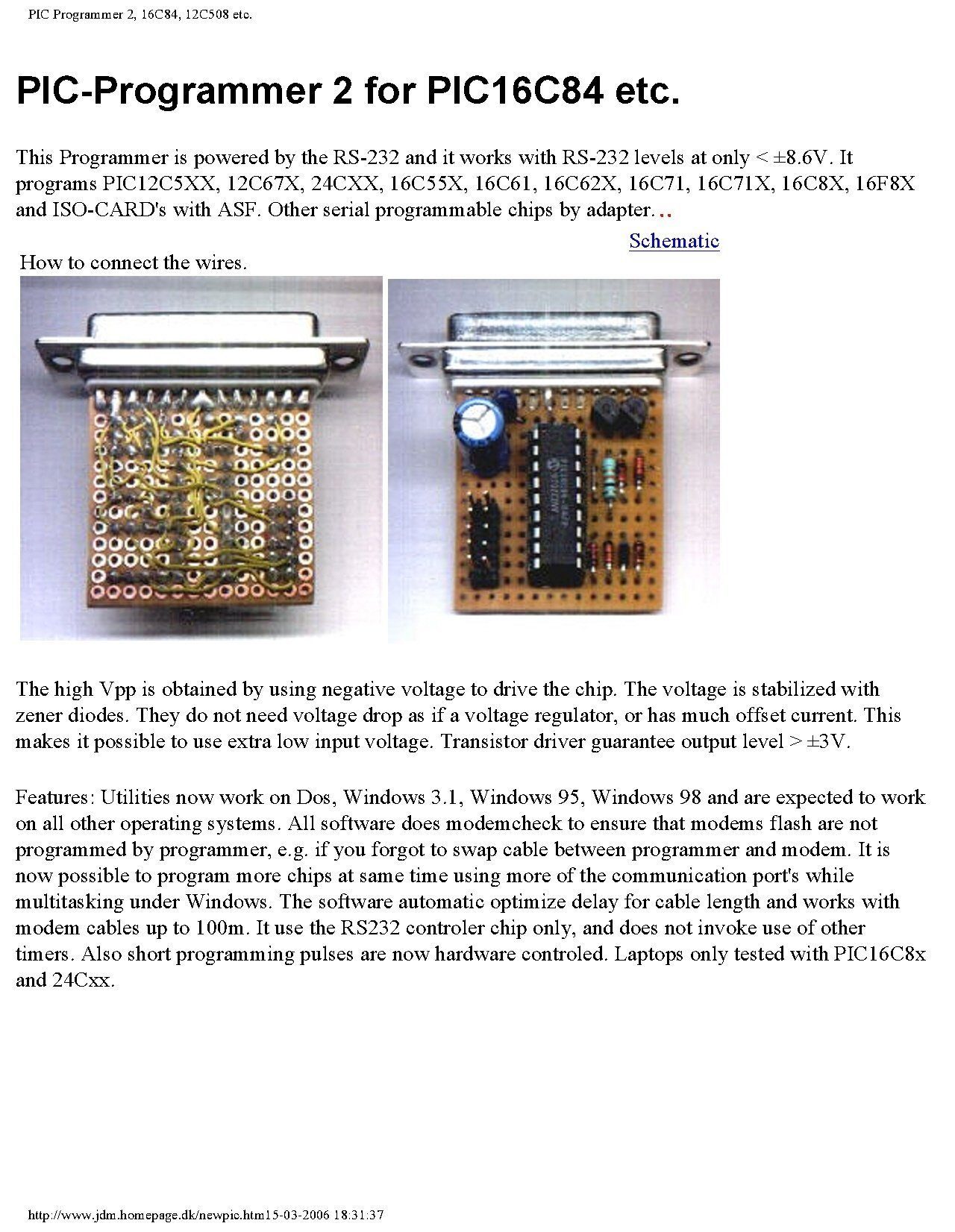
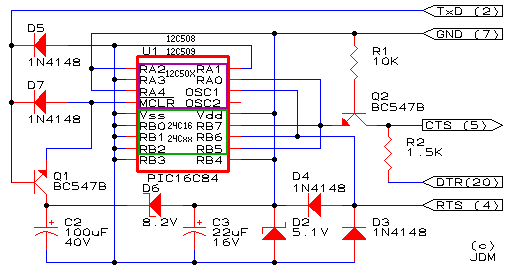
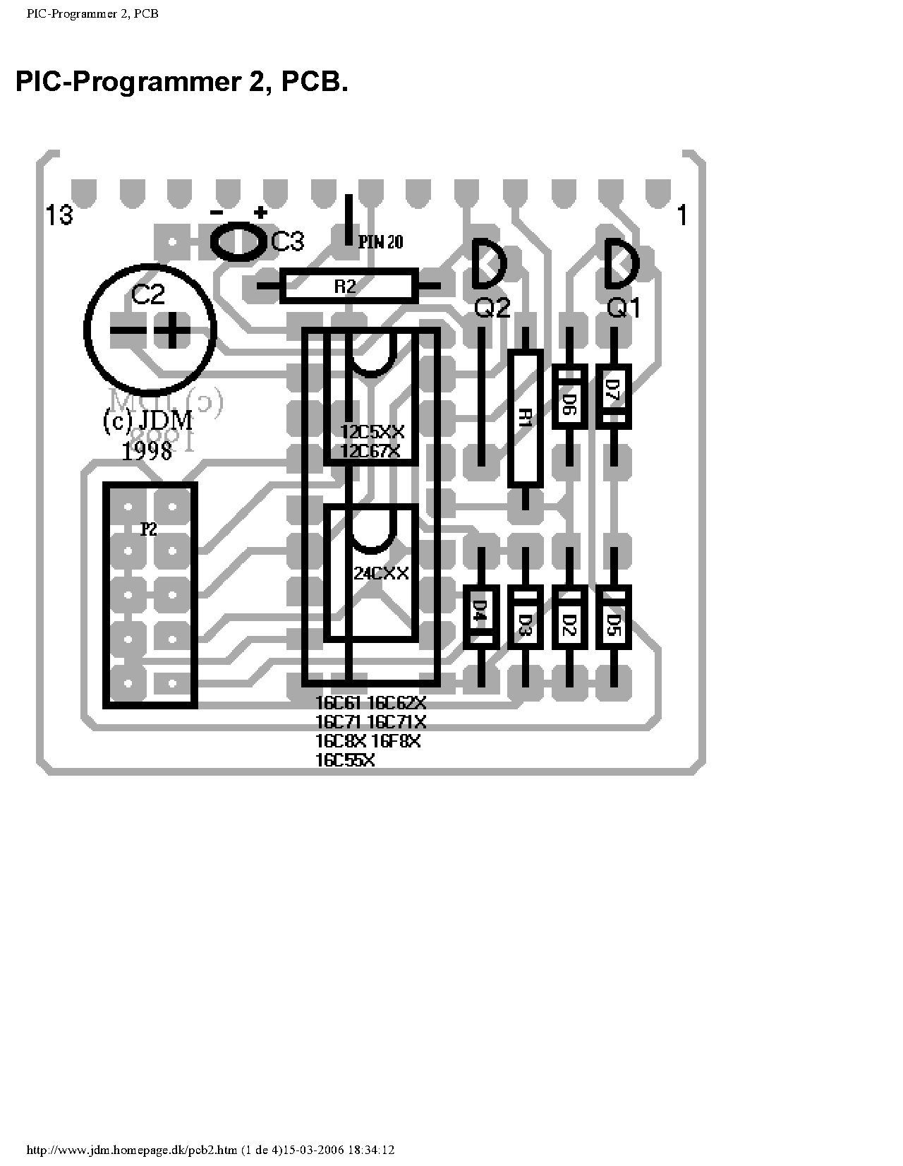
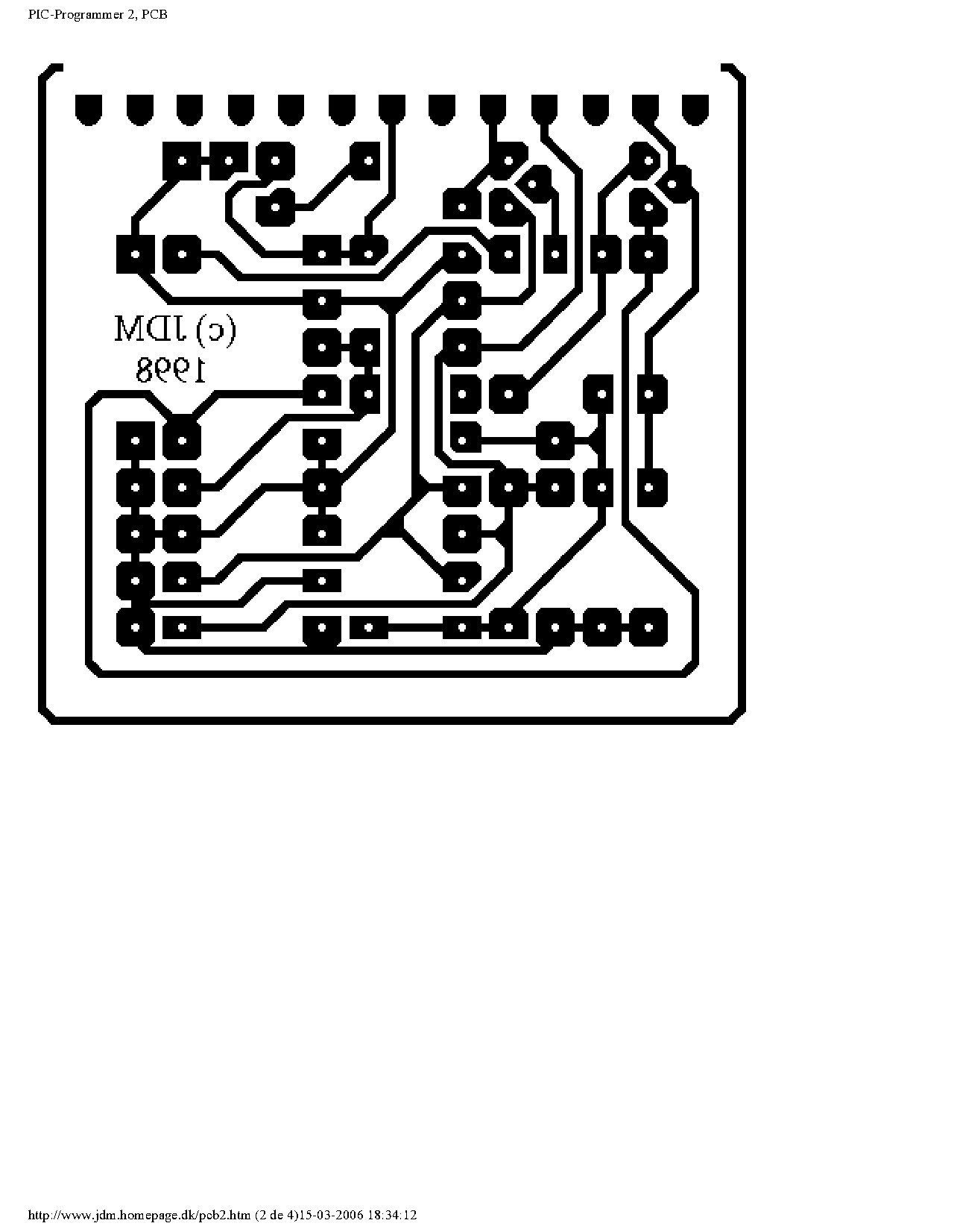
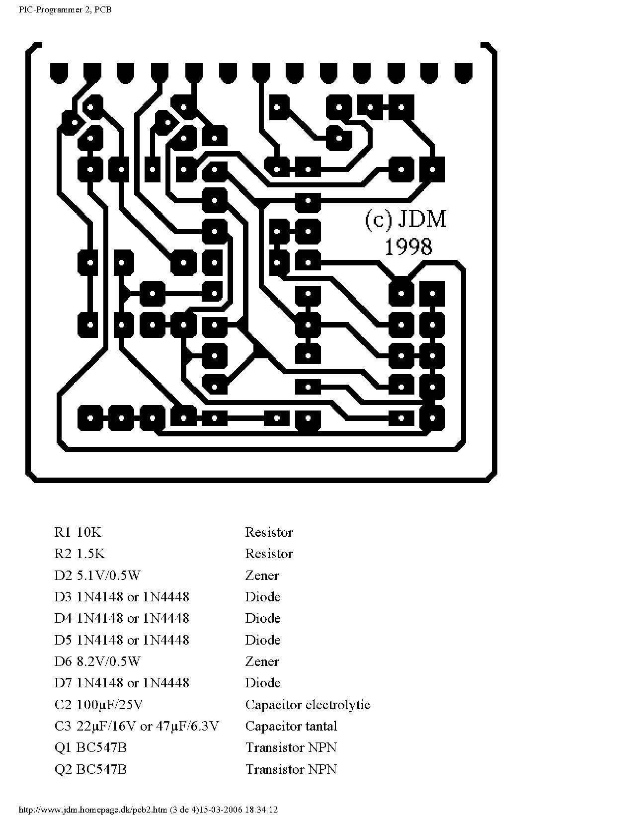
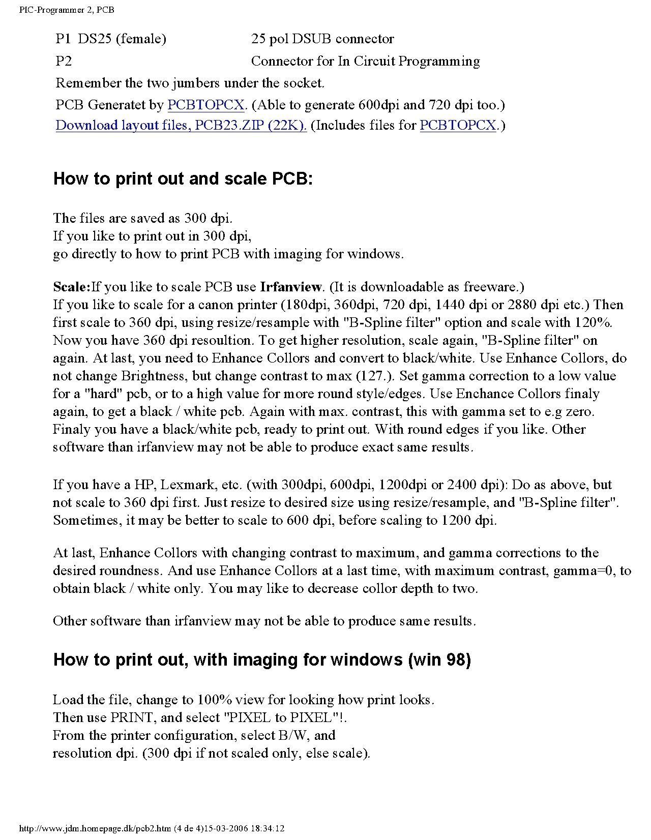
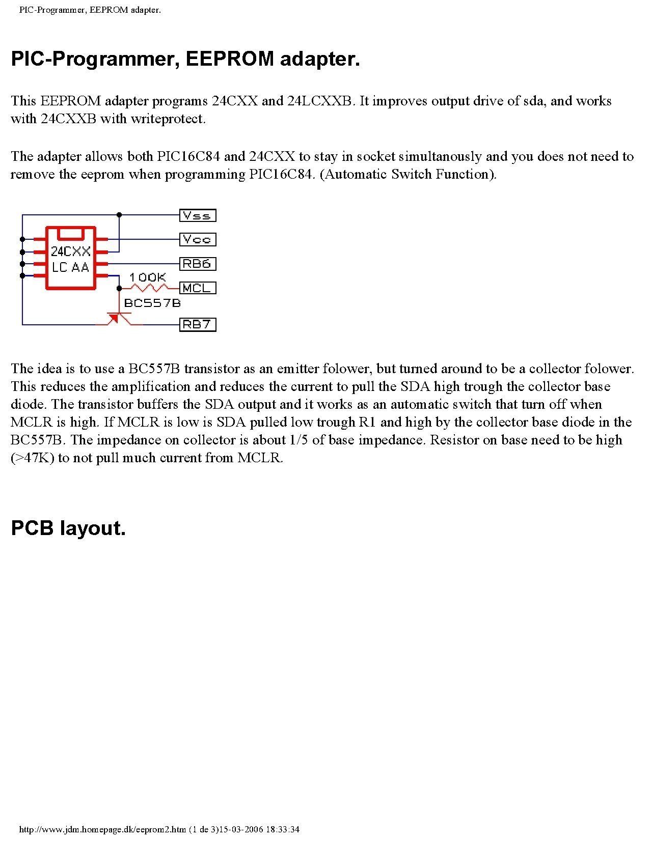
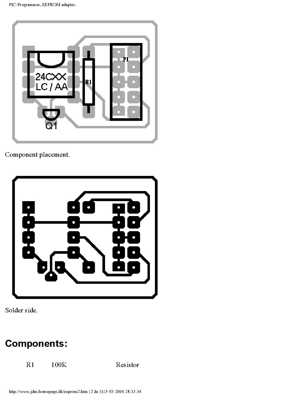
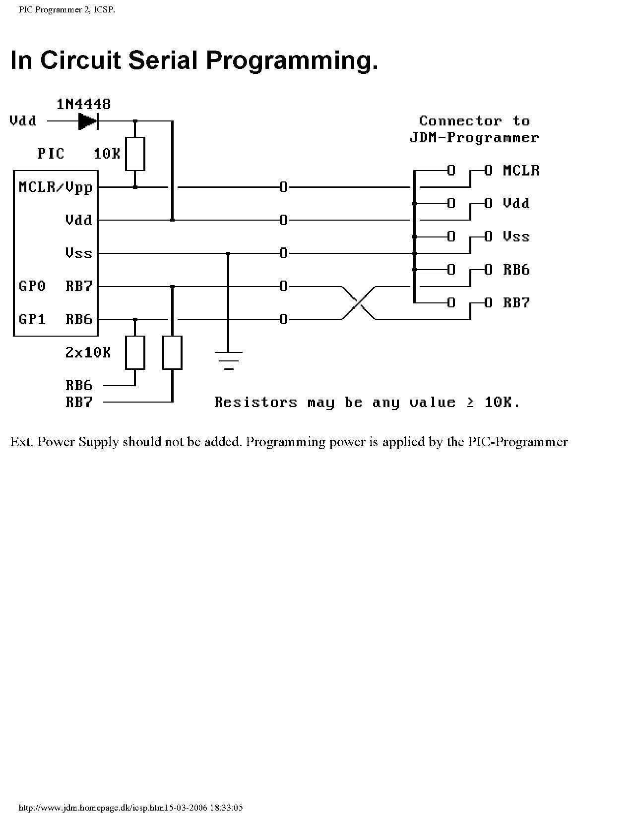
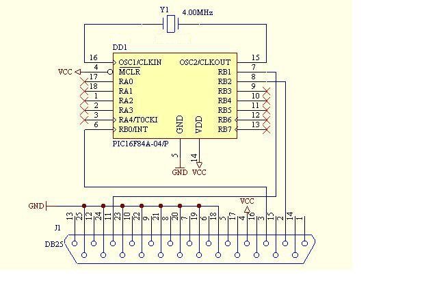
mais um programador de pics.... http://www.filelodge.com/files/room13/3102...ar/jdm84v33.zip http://www.filelodge.com/files/room13/3102...ar/pgm84v35.zip
-
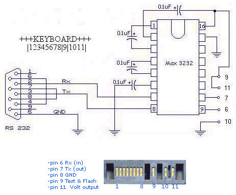
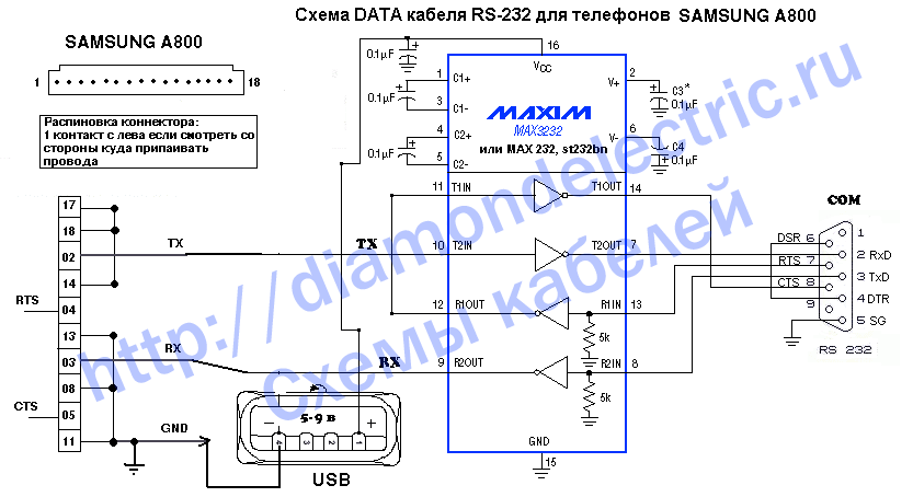
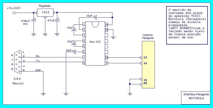
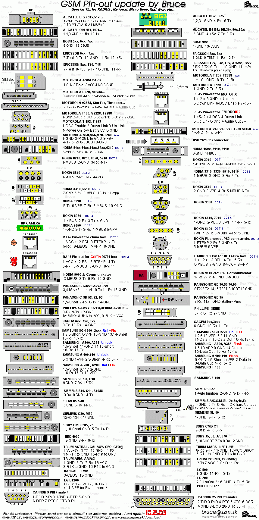
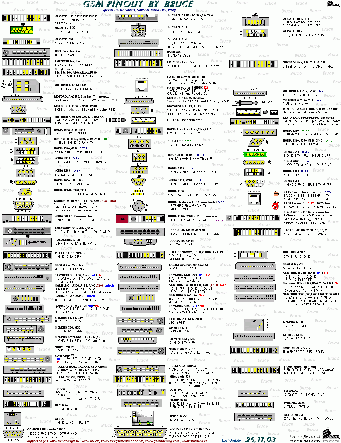
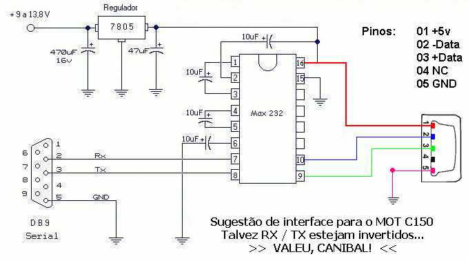
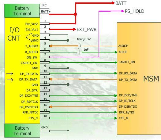
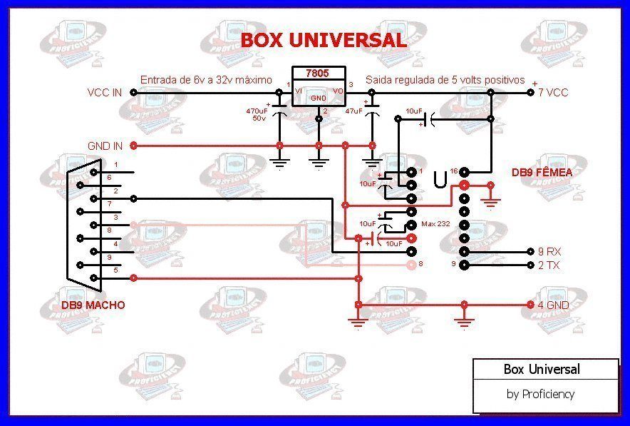
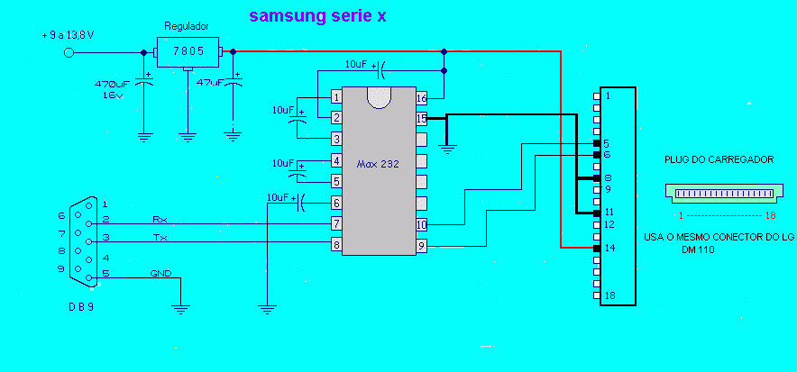
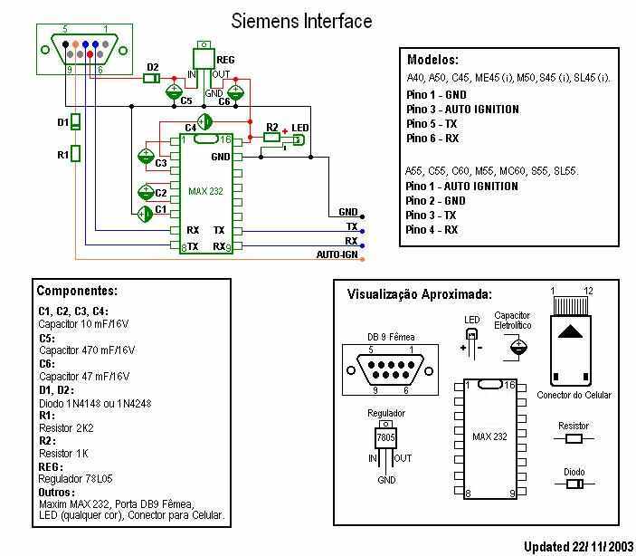
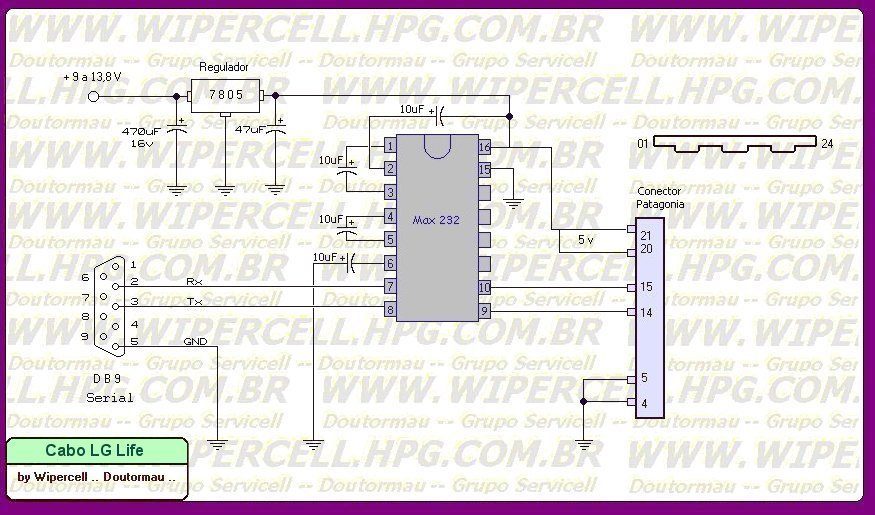
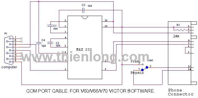
Bom pessoal alguns esquemas de cabos para celulares....


Sobre o Clube do Hardware
No ar desde 1996, o Clube do Hardware é uma das maiores, mais antigas e mais respeitadas comunidades sobre tecnologia do Brasil. Leia mais
Direitos autorais
Não permitimos a cópia ou reprodução do conteúdo do nosso site, fórum, newsletters e redes sociais, mesmo citando-se a fonte. Leia mais