

Eduardo Carbonari
-
Posts
4 -
Cadastrado em
-
Última visita
-
Prezados Estou apreendendo sobre linguagem C. e gostaria de saber o que significa o símbolo ! e ação que faz na flag do ccp2 Por exemplo: if ((! pir2_ccp2if)) then Desde já obrigado
-
PIC motor de passo com pic 16f877 só gira num sentido
Eduardo Carbonari respondeu ao tópico de Eduardo Carbonari em Microcontroladores
Prezada Isadora Acredito que a sequencia esteja correta, pois se aciono as bobinas aleatoriamente, o motor gira desritmado. A ordem em que esta no código, realmente o motor gira no sentido anti-horário. Tentei e presumi invertendo a sequencia do código que postei o motor giraria para o sentido horário. Mas ao contrario ele continua girando no sentido anti-horário. -
PIC motor de passo com pic 16f877 só gira num sentido
Eduardo Carbonari postou um tópico em Microcontroladores
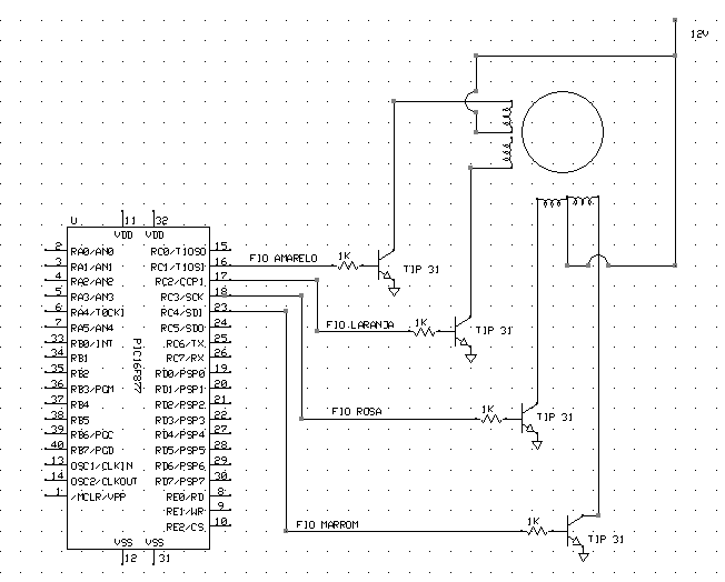
Prezados Estou começando a trabalhar com motor de passo. Elaborei o código em assembly. Mas o motor só gira para o sentido anti-horário, mesmo invertendo a sequencia das bobinas. Estou disponibilizando o código e o esquema elétrico. Deste já agradeço a ajuda. <;;;;;;;;;;;;;;;;;;;;;;;;;;;;;;;;;;;;;;;;;;;;;;;;;;;;;;;;;;;;;;;;;;;;;;;;;;;;;;;;;;;;;;;;;;;;;;;;;;;;;;;;;;;;;;;;;;;;;;;;;;;;;;;;;;;;;;;;;;;;;;;;;;;;;;;;;;;;;;;;;;;;;;;;;;;;;;;;;;;;;;;;;;;;;;;;;;;;;;;;;;; LIST P=16F877 ;Definição do PIC #INCLUDE <P16F877.INC> ;Variaveis das definições do PIC __CONFIG _CP_OFF & _DEBUG_ON & _WDT_OFF & _BODEN_OFF & _PWRTE_OFF & _HS_OSC & _LVP_OFF & _CPD_OFF ;;;;;;;;;;;;;;;;;;;;;;;;;;;;;;;;;;;;;;;;;;;;;;;;;;;;;;;;;;;;;;;;;;;;;;;;;;;;;;;;;;;;;;;;;;;;;;;;;;;;;;;;;;;;;;;;;;;;;;;;;;;;;;;;;;;;;;;;;;;;;;;;;;;;;;;;;;;;;;;;;;;;;;;;;;;;;;;;;;;;;;;;;;;;;;;;;;;;;;;;;;;;; VARIAVEL_DO_TEMPORIZADOR SET 0x20 T1 equ 0x21 ;variável para temporizador T2 equ 0x22 ;variável para temporizador T3 equ 0x23 ;variável para temporizador T4 equ 0x24 ;variável para temporizador AUX equ 0x25 ;variável para dado recebido RESET ORG 0X000 ;Area de Reset do PIC NOP ;Requerido para o ICD configuração banksel TRISC ;Muda para o BANK 1 bcf TRISC,2 ;Configura apenas a PORTC1 como saida ;FIO LARANJA bcf TRISC,3 ;Configura apenas a PORTC3 como saida ;FIO ROSA bcf TRISC,4 ;Configura apenas a PORTC4 como saida ;FIO MARROM bcf TRISC,1 ;Configura apenas a PORTC5 como saída ;FIO AMARELO movlw b'00000111' ;Configura as portas A/D movwf ADCON1 banksel PORTC ;Volta para o BANK 0 INICIO ;PRIMEIRO PASSO bsf PORTC,1 ;FIO AMARELO call TEMPORIZADOR bcf PORTC,1 ;FIO AMARELO call TEMPORIZADOR ;call _1000ms ;aguarda 1 segundo CICLO ;SEGUNDO PASSO bsf PORTC,2 ;FIO LARANJA call TEMPORIZADOR bcf PORTC,2 ;FIO LARANJA call TEMPORIZADOR ;call _1000ms ;aguarda 1 segundo ;TERCEIRO PASSO bsf PORTC,4 ;FIO MARROM call TEMPORIZADOR bcf PORTC,4 ;FIO MARROM call TEMPORIZADOR ;call _1000ms ;aguarda 1 segundo ;QUARTO PASSO bsf PORTC,3 ;FIO ROSA call TEMPORIZADOR bcf PORTC,3 ;FIO ROSA call TEMPORIZADOR goto INICIO TEMPORIZADOR movwf VARIAVEL_DO_TEMPORIZADOR TEMPORIZADOR_0 decfsz VARIAVEL_DO_TEMPORIZADOR,F goto TEMPORIZADOR_1 return TEMPORIZADOR_1 addlw .1 btfss STATUS,Z goto TEMPORIZADOR_1 goto TEMPORIZADOR_0 ;;;;;;;;;;;;;;;;;;;;;;;;;;;;;;;;;;;;;;;;;;;;;;;;;;;;;;;;;;;;;;;;;;;;;;;;;;;;;;;;;;;;;;;;;;;;;;;;;;;;;;;;;;;;;;;;;;;;;;;;;;;;;;;;;;;;;;;;;;;;;;;;;;;;;;;;;;;;;;;;;;;;;;;;;;;;;;;;;;;;;;;;;;;;;;;;;;;;;;; end>
-
Olá Estou tentando o PIC16F628A na porta serial, mas o código que possuo esta configurado para se comunicar com o Transmissor/Receptor DS232, no qual sua característica é sua velocidade de transmissão e recepção é de 250 kbits/sec. O problema é que não se encontra este componente facilmente, pelo menos onde moro. Então estou tentando adaptar para o MAX232. Mas estou tendo problema para configurar o valor baud rate. Estou postando o código fonte e o oscilador é externo de 20MHZ se alguém puder me auxiliar agradeço. ;Program Listing #include <P16F628A.inc> list p = PIC16F628A __config H'3FAA' ; this config gives us LVP and enables /MCLR errorlevel -302 ; do not print message for operands that are not in bank 0 ; define the baud rate for the hardware UART #define BAUD_VALUE 0x15 ; 0x15 sets the baud rate to 57600 with a 20.0MHz crystal #define SCL PORTA,1 ; bus clock line #define SDA PORTA,4 ; bus data line SCRATCH equ 0x40 ; 1 by general-purpose scratchpad TMP equ 0x41 ; temp register TMP2 equ 0x42 ; temp register COUNT equ 0x43 YRS equ 0x44 MON equ 0x45 DOW equ 0x46 DAYS equ 0x47 HRS equ 0x48 MINS equ 0x49 SECS equ 0x4a SET_BANK0 MACRO bcf STATUS, RP0 bcf STATUS, RP1 ENDM SET_BANK1 MACRO bsf STATUS, RP0 bcf STATUS, RP1 ENDM I2C_START MACRO bsf SDA ; SDA high nop SET_BANK1 bsf TRISA, 1 ; SCL high (input) SET_BANK0 bcf SDA ; SDA low (start) ENDM I2C_STOP MACRO ; assumes SCL is high on entry bcf SDA ; SDA low nop nop SET_BANK1 bsf TRISA, 1 ; SCL high (input) SET_BANK0 bsf SDA ; SDA high ENDM org 0x00 RESET: goto START ;----------------------------------------- ;--------------- start --------------- ;----------------------------------------- org 0x0A START: SET_BANK0 clrf PORTA ; initialize PORTA movlw 0x07 movwf CMCON ; turn off the comparator for PORTA SET_BANK1 movlw 0x00 movwf VRCON ; turn off the voltage-reference module movlw 0x10 ; RA4 read (High Z) movwf TRISA ; set pins for input or output SET_BANK0 call uart_init CheckForCommands: movlw banner-1 ; move label address into W register call write ; print string starting at address of label call uart_getchar ; returns character in W call uart_putchar ; echo movwf TMP bcf TMP,5 ; convert to upper case movf TMP,W ; put back in W xorlw 'S' ; write to RTC btfss STATUS,Z goto not_ss call set_clock ; set the clock using data from user goto CheckForCommands not_ss: movf TMP,W ; retrieve character xorlw 'R' ; read from RTC btfss STATUS,Z goto not_rr call read_clock ; display time and date by using the serial port goto CheckForCommands not_rr: goto CheckForCommands ;----------------------------------------- ;--- UART routines --- ;----------------------------------------- ;---- send a byte through the serial port ---- uart_putchar: charwait1: btfss PIR1, TXIF goto charwait1 movwf TXREG return ;---- get a byte from the serial port ---- uart_getchar: charwait2: btfss PIR1, RCIF ; is data available? goto charwait2 ; if not, then wait movfw RCREG return ;----- initialize the serial port ----- uart_init: SET_BANK1 movlw BAUD_VALUE ; set the baud rate movwf SPBRG ; move baudreg into SPBRG, set baud rate bcf TXSTA, SYNC ; clear SYNC bit, asynchronous mode bsf TXSTA, BRGH ; BRGH = 1, high-speed SP mode. bsf TXSTA, TXEN ; enable transmission bcf PIE1, RCIE ; disable serial-port interrupt SET_BANK0 bsf RCSTA, SPEN ; set SPEN bit, serial-port enable bsf RCSTA, CREN ; set CREN bit, serial-port receive enable return ; return ;---------------------------------------- ;-- text strings for user interface -- ;---------------------------------------- banner: dt "\n\rDS1307 DEMO\n\rR)ead time S)et time\n\r",0h year: dt "\n\rYear (0-99): ",0h month: dt "Month (1-12): ",0h dow: dt "Day of Week (1-7): ",0h date: dt "Date (1-28,29,30,31): ",0h hour: dt "Hour (0-23): ",0h minute: dt "Minute (0-59): ",0h second: dt "Second (0-59): ",0h ;----------------------------------------- ;-- character conversion routines -- ;----------------------------------------- ;--------- ASCII to bcd ---------- readbcd: clrf TMP ; clear temp reg gobcd: call uart_getchar ; returns character in W call uart_putchar ; echo to screen xorlw 0dh ; if cr, Z will be set btfss STATUS,Z ; skip if clear goto bcd ; go to bcd if Z = 0 movf TMP,W ; done, move final value to W return ; and return bcd: xorlw 0dh ; restore value addlw -30h ; subtract ASCII offset btfsc W,4 ; jump if not A-F addlw -7 ; if A-F, subtract 7 digit: andlw 0x0f ; clear upper nibble bcf TMP,4 ; clear upper nibble of temp reg bcf TMP,5 bcf TMP,6 bcf TMP,7 movwf SCRATCH ; save W movf TMP,W ; copy TMP to W movwf TMP2 ; save TMP movf SCRATCH,W ; restore W movwf TMP ; TMP now has org W value movf TMP2,W ; W now has org TMP value swapf TMP2,W ; swap nibbles iorwf TMP,W ; insert bits 0 to 3 of TMP to W movwf TMP ; move W into temp reg goto gobcd ; continue until CR is encountered ;-- convert bcd to ASCII -- ;-- entry: W=bcd value exit: W = last ASCII -- writebcd: movwf TMP ; save W swapf TMP,W ; swap nibbles andlw 0x0f ; clear bits 4 to 7 addlw 0x06 ; add 6 btfss STATUS,DC ; if a-f, DC = 1 goto lessnine ; if DC = 0, < 9, so go to lessnine addlw 0x31 ; add 31h to make ASCII goto digit1 ; skip to output lessnine: addlw 0x2a ; add offset for bits 0 to 9 to make ASCII digit1: call uart_putchar ; print char movf TMP,W ; restore W andlw 0x0f ; clear bits 4 to-7 addlw 0x06 ; add 6 btfss STATUS,DC ; if a-f, DC = 1 goto lessnine2 ; if DC = 0, < 9, so go to lessnine2 addlw 0x31 ; add 31h to make ASCII goto digit2 ; skip to output lessnine2: addlw 0x2a ; add offset for bits 0-to 9 to make ASCII digit2: call uart_putchar ; print char return ;--------------------------------------------- ;-- display RTC data -- ;--------------------------------------------- read_clock: call RTC_brst_rd ; get the data from the RTC read_regs: movf YRS,W call writebcd movlw '/' call uart_putchar movf MON,W call writebcd movlw '/' call uart_putchar movf DAYS,W call writebcd movlw ' ' call uart_putchar movf DOW,W call writebcd movlw ' ' call uart_putchar movf HRS,W call writebcd movlw ':' call uart_putchar movf MINS,W call writebcd movlw ':' call uart_putchar movf SECS,W call writebcd movlw 0x0d ; cr call uart_putchar return ;--------------------------------------------- ;-- write to the RTC with user-entered data -- ;--------------------------------------------- set_clock: movlw year-1 ; prompt user for data (year) call write call readbcd ; get the data movwf YRS ; save it movlw month-1 ; prompt user for data (month) call write call readbcd movwf MON movlw date-1 ; prompt user for data (month) call write call readbcd movwf DAYS movlw dow-1 ; prompt user for data (month) call write call readbcd movwf DOW movlw hour-1 ; prompt user for data (month) call write call readbcd movwf HRS movlw minute-1 ; prompt user for data (month) call write call readbcd movwf MINS movlw second-1 ; prompt user for data (month) call write call readbcd movwf SECS call RTC_brst_wr ; now write data to RTC return ;----------------------------------------- ;-- RTC routines -- ;----------------------------------------- RTC_brst_rd: I2C_START movlw 0D0h ; slave address + write call write_RTC movlw 0 ; set word address to seconds register call write_RTC I2C_START movlw 0D1h ; slave address + read call write_RTC call read_RTC ; read the seconds data movwf SECS ; save it call ack; call read_RTC ; and so on movwf MINS call ack; call read_RTC movwf HRS call ack; call read_RTC movwf DOW call ack; call read_RTC movwf DAYS call ack; call read_RTC movwf MON call ack; call read_RTC movwf YRS call nack; I2C_STOP return RTC_brst_wr: I2C_START movlw 0D0h ; slave address + write call write_RTC movlw 0 ; set word address to seconds register call write_RTC movf SECS, W call write_RTC movf MINS, W call write_RTC movf HRS, W call write_RTC movf DOW, W call write_RTC movf DAYS, W call write_RTC movf MON, W call write_RTC movf YRS, W call write_RTC I2C_STOP return ;---- Read RTC into W ---- read_RTC: SET_BANK1 bsf TRISA,4 ; set SDA for input SET_BANK0 movlw 08h ; send 8 bits movwf COUNT bcf SCL ; clock data out SET_BANK1 bcf TRISA, 1 ; SCL low (output) SET_BANK0 clrf TMP ; clear var rlf TMP, 1 ; rotate carry in clrf TMP ; clear var again I2C_read_loop: rlf TMP, 1 SET_BANK1 bsf TRISA, 1 ; SCL high (input) SET_BANK0 btfsc SDA bsf TMP, 0 ; if data out = 1, set bit bcf SCL SET_BANK1 bcf TRISA, 1 ; SCL low (output) SET_BANK0 decfsz COUNT, 1 goto I2C_read_loop movf TMP, W return ;---- ACK read (assumes SCL=0 on entry) ---- ack: bcf SDA SET_BANK1 bcf TRISA,4 ; set SDA for output SET_BANK0 SET_BANK1 bsf TRISA, 1 ; SCL high (input) SET_BANK0 nop bcf SCL SET_BANK1 bcf TRISA, 1 ; SCL low (output) SET_BANK0 return ;---- NACK read (assumes SCL = 0 on entry) ---- nack: bsf SDA SET_BANK1 bcf TRISA,4 ; set SDA for output SET_BANK0 SET_BANK1 bsf TRISA, 1 ; SCL high (input) SET_BANK0 bcf SCL SET_BANK1 bcf TRISA, 1 ; SCL low (output) SET_BANK0 return ;--- Write the byte in W to RTC --- ;---- assumes CE is asserted ---- write_RTC: movwf TMP ;Save the data ; ;--- Do a I2C bus write of byte in 'TMP' --- ; I2C_write: SET_BANK1 bcf TRISA, 4 ; set SDA for output SET_BANK0 movlw 08h ; send 8 bits movwf COUNT bcf SCL SET_BANK1 bcf TRISA, 1 ; SCL low (output) SET_BANK0 I2C_w_loop: bcf SDA ; assume data out is low btfsc TMP, 7 bsf SDA ; if data out = 1, set bit ; nop SET_BANK1 bsf TRISA, 1 ; SCL high (input) SET_BANK0 rlf TMP, 1 bcf SCL ; clock it in SET_BANK1 bcf TRISA, 1 ; SCL low (output) SET_BANK0 decfsz COUNT, 1 goto I2C_w_loop SET_BANK1 bsf TRISA,4 ; set SDA for input SET_BANK0 bcf SCL SET_BANK1 bcf TRISA, 1 ; SCL low (output) SET_BANK0 ; nop SET_BANK1 bsf TRISA, 1 ; SCL high (input) SET_BANK0 ; if(sda) printf("Ack bit missing %02X\n",(unsigned int)d); bcf SCL SET_BANK1 bcf TRISA, 1 ; SCL low (output) SET_BANK0 return ;----------------------------------------- ;-- pclsub used for indirect addressing -- ;----------------------------------------- pclsub: incf SCRATCH,F ; advance table pointer movf SCRATCH,W ; move table pointer to W movwf PCL ; jump to address pointed by PCLATH,W ;---------------------------------------- ;-- write a string to USART -- ;---------------------------------------- write: movwf SCRATCH ; FSR = string address GoWrite: call pclsub ; advance pointer and read pointed byte addlw 0h ; if contents are zero, Z will be set btfsc STATUS,Z ; skip if clear return ; current character is null: end of string call uart_putchar ; print one character goto GoWrite ; loop end


Sobre o Clube do Hardware
No ar desde 1996, o Clube do Hardware é uma das maiores, mais antigas e mais respeitadas comunidades sobre tecnologia do Brasil. Leia mais
Direitos autorais
Não permitimos a cópia ou reprodução do conteúdo do nosso site, fórum, newsletters e redes sociais, mesmo citando-se a fonte. Leia mais