

Nícolas Ludwig
-
Posts
3 -
Cadastrado em
-
Última visita
-
Estou testando comunicar o módulo RF 433Mhz via USART, usando o PIC18F4550. Instalei os arquivos deste módulo no Proteus 8 e simulando no programa funcionou normalmente. Já no físico (protoboard), não funcionou. A função do código é simplesmente enviar um char por serial e recebê-lo no mesmo PIC para ligar ou desligar o LED. No meu caso, o LED permanece sempre desligado. Já no Proteus, ele fica piscando. Utilizo o MPLAB IDE com compilador XC8, e estou utilizando a biblioteca usart.h da PLIB. O baud rate que configurei foi de 4800, tanto no Proteus como no MPLAB. Utilizo cristal de 20Mhz, mas configurei para FOSC de 48Mhz utilizando PLL. Segue abaixo o código para MPLAB e Proteus, e em anexo está os arquivos do Proteus. #include <xc.h> #include <stdio.h> #include <stdlib.h> #include <plib/usart.h> #define _XTAL_FREQ 20000000 // CONFIG1L #pragma config PLLDIV = 5 // PLL Prescaler Selection bits (No prescale (4 MHz oscillator input drives PLL directly)) #pragma config CPUDIV = OSC1_PLL2// System Clock Postscaler Selection bits ([Primary Oscillator Src: /1][96 MHz PLL Src: /2]) #pragma config USBDIV = 2 // USB Clock Selection bit (used in Full-Speed USB mode only; UCFG:FSEN = 1) (USB clock source comes directly from the primary oscillator block with no postscale) // CONFIG1H #pragma config FOSC = HSPLL_HS // Oscillator Selection bits (HS oscillator (HS)) #pragma config FCMEN = OFF // Fail-Safe Clock Monitor Enable bit (Fail-Safe Clock Monitor disabled) #pragma config IESO = OFF // Internal/External Oscillator Switchover bit (Oscillator Switchover mode disabled) // CONFIG2L #pragma config PWRT = OFF // Power-up Timer Enable bit (PWRT disabled) #pragma config BOR = OFF // Brown-out Reset Enable bits (Brown-out Reset disabled in hardware and software) #pragma config BORV = 1 // Brown-out Reset Voltage bits (Setting 2 4.33V) #pragma config VREGEN = OFF // USB Voltage Regulator Enable bit (USB voltage regulator disabled) // CONFIG2H #pragma config WDT = OFF // Watchdog Timer Enable bit (WDT disabled (control is placed on the SWDTEN bit)) #pragma config WDTPS = 32768 // Watchdog Timer Postscale Select bits (1:32768) // CONFIG3H #pragma config CCP2MX = OFF // CCP2 MUX bit (CCP2 input/output is multiplexed with RB3) #pragma config PBADEN = OFF // PORTB A/D Enable bit (PORTB<4:0> pins are configured as digital I/O on Reset) #pragma config LPT1OSC = OFF // Low-Power Timer 1 Oscillator Enable bit (Timer1 configured for higher power operation) #pragma config MCLRE = OFF // MCLR Pin Enable bit (RE3 input pin enabled; MCLR pin disabled) // CONFIG4L #pragma config STVREN = OFF // Stack Full/Underflow Reset Enable bit (Stack full/underflow will not cause Reset) #pragma config LVP = OFF // Single-Supply ICSP Enable bit (Single-Supply ICSP disabled) #pragma config ICPRT = OFF // Dedicated In-Circuit Debug/Programming Port (ICPORT) Enable bit (ICPORT disabled) #pragma config XINST = OFF // Extended Instruction Set Enable bit (Instruction set extension and Indexed Addressing mode disabled (Legacy mode)) // CONFIG5L #pragma config CP0 = OFF // Code Protection bit (Block 0 (000800-001FFFh) is not code-protected) #pragma config CP1 = OFF // Code Protection bit (Block 1 (002000-003FFFh) is not code-protected) #pragma config CP2 = OFF // Code Protection bit (Block 2 (004000-005FFFh) is not code-protected) #pragma config CP3 = OFF // Code Protection bit (Block 3 (006000-007FFFh) is not code-protected) // CONFIG5H #pragma config CPB = OFF // Boot Block Code Protection bit (Boot block (000000-0007FFh) is not code-protected) #pragma config CPD = OFF // Data EEPROM Code Protection bit (Data EEPROM is not code-protected) // CONFIG6L #pragma config WRT0 = OFF // Write Protection bit (Block 0 (000800-001FFFh) is not write-protected) #pragma config WRT1 = OFF // Write Protection bit (Block 1 (002000-003FFFh) is not write-protected) #pragma config WRT2 = OFF // Write Protection bit (Block 2 (004000-005FFFh) is not write-protected) #pragma config WRT3 = OFF // Write Protection bit (Block 3 (006000-007FFFh) is not write-protected) // CONFIG6H #pragma config WRTC = OFF // Configuration Register Write Protection bit (Configuration registers (300000-3000FFh) are not write-protected) #pragma config WRTB = OFF // Boot Block Write Protection bit (Boot block (000000-0007FFh) is not write-protected) #pragma config WRTD = OFF // Data EEPROM Write Protection bit (Data EEPROM is not write-protected) // CONFIG7L #pragma config EBTR0 = OFF // Table Read Protection bit (Block 0 (000800-001FFFh) is not protected from table reads executed in other blocks) #pragma config EBTR1 = OFF // Table Read Protection bit (Block 1 (002000-003FFFh) is not protected from table reads executed in other blocks) #pragma config EBTR2 = OFF // Table Read Protection bit (Block 2 (004000-005FFFh) is not protected from table reads executed in other blocks) #pragma config EBTR3 = OFF // Table Read Protection bit (Block 3 (006000-007FFFh) is not protected from table reads executed in other blocks) // CONFIG7H #pragma config EBTRB = OFF // Boot Block Table Read Protection bit (Boot block (000000-0007FFh) is not protected from table reads executed in other blocks) void Mydelay(int tempo) { int i; for (i=0;i<tempo;i++) { __delay_ms(1); } } void main(void) { ADCON1 = 0x0F; TRISD = 0; OpenUSART( USART_TX_INT_OFF & // No tx interrupt. USART_RX_INT_ON & // No rcv interrupt. USART_ASYNCH_MODE & // Asynchronous mode. USART_EIGHT_BIT & // Eight-bit mode. USART_CONT_RX & // Continuous receive. USART_BRGH_LOW, // Use low speed baud rate formula. 155 // Baud 4800 ); Mydelay(100); unsigned char teste = 'a'; unsigned char ch = 'a'; int cont = 0; while(1) { WriteUSART(teste); //Mydelay(5); ch = ReadUSART(); if(ch=='a') LATDbits.LD7 = 1; else LATDbits.LD7 = 0; Mydelay(1000); if(cont == 1) { teste = 'b'; cont = 0; } else { teste = 'a'; cont = 1; } } return; } Agradeço quem puder ajudar! RF Proteus.rar
-
Muito obrigado pelas respostas! Ótima explicação MOR. Abraço
-
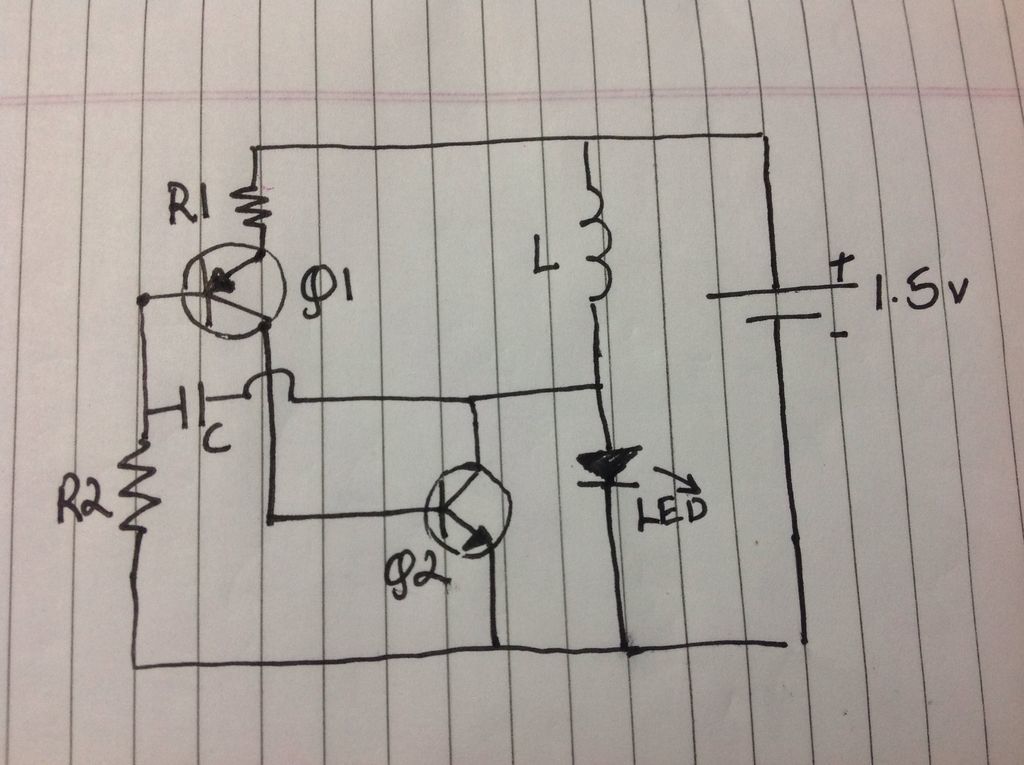
Estou em dúvida neste circuito de Ladrão de Joule que achei no site Instructables. Já vi vários tipos desse circuito, com toróides e transformadores, mas esse é apenas com um indutor padrão e um capacitor. Alguém pode me explicar o funcionamento de cada componente neste circuito? O projeto e o esquemático se encontram nesse link: https://www.instructables.com/id/Super-Simple-Inductor-Joule-Thief/ Coloquei em anexo também. Componentes (em inglês, retirado do link acima): - LED - Any colour will do, however colours like green and blue work best - Transistors - 1 NPN (BC547) and 1 PNP (BC557) - Resistors - 1K ohm * 1 and 33K ohm * 1 - Capacitor - 0.01uF ceramic capacitor - Inductor - Anything between 220uH and 510uH (I used 470uH) - AA battery - or any battery giving less than 1.5volts Obrigado!

Sobre o Clube do Hardware
No ar desde 1996, o Clube do Hardware é uma das maiores, mais antigas e mais respeitadas comunidades sobre tecnologia do Brasil. Leia mais
Direitos autorais
Não permitimos a cópia ou reprodução do conteúdo do nosso site, fórum, newsletters e redes sociais, mesmo citando-se a fonte. Leia mais