
Bruno R Ruinho
-
Posts
117 -
Cadastrado em
-
Última visita
Tipo de conteúdo
Artigos
Selos
Livros
Cursos
Análises
Fórum
Tudo que Bruno R Ruinho postou
-

Criar uma fonte automotiva através de um trafo de 7a
Bruno R Ruinho respondeu ao tópico de Pedro R7 Lima em Eletrônica
Esta fonte ja foi testada e aprovada por varios membros do Forum, eu nao tive sucesso com o LM338 mas pode ser substituido pelo LM317 e adicionar transistores para o ganho na potencia. \ Como voce vai querer uma saida fixa, pode usar como na foto, um trimpot, e regular para os 13.8v Espero ter ajudado!
-
Estou montando com o LM317 e o TIP147, estou esperando chegar, pois tinha o TIP 142 mas ele é NPN nao dava certo. Acho que amanha ja posto novidades!
-
Sim, a tensão em aberto esta em 1,2V quando coloco o resistor cai para 1V, estou achando estranho esse comportamento, a falta dos capacitores de tântalo não é para interferir no funcionamento...
-
Bom montei novamente o circuito! Ele esta variando normalmente, mas agora quando consumo alguma corrente a tensão cai muito, fiz um vídeo para a prova:
-
Exato igual voce tinha falado no post da fonte " E um CI contra idiotas" impossivel fazer algo de estão errado para ele queimar, fiz o teste sem o dissipador pois fazia 5 min que o LM com dissipador tinha queimado, ele estava estão bem montado que nao desmontei... Vou refazer a montagem amanha nao inverti o Vout pelo Vadj. pois ele esta variando normalmente, o problema e quando eu coloco o resistor de 0.22R a saida zera. E nao volta por nada! Logo o LM queimou! Estou usando uma fonte variavel como entrada, estou colocando 20V e regulando a fonte para limitar a corrente em 3A, devo mudar a carga para teste? usar uma lampada ou um resistor maior? Ou de alguma forma estou alimentando o LM errado? Ainda desconfio que esses LM338 que comprei sao de ma qualidade...
-
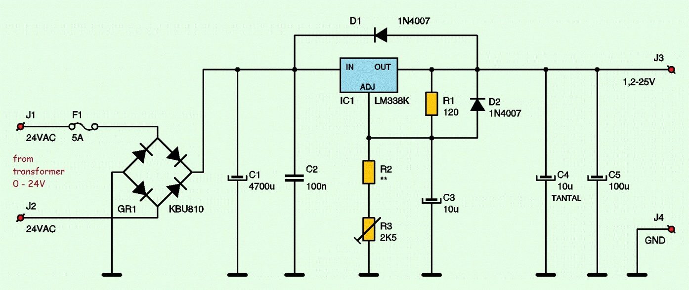
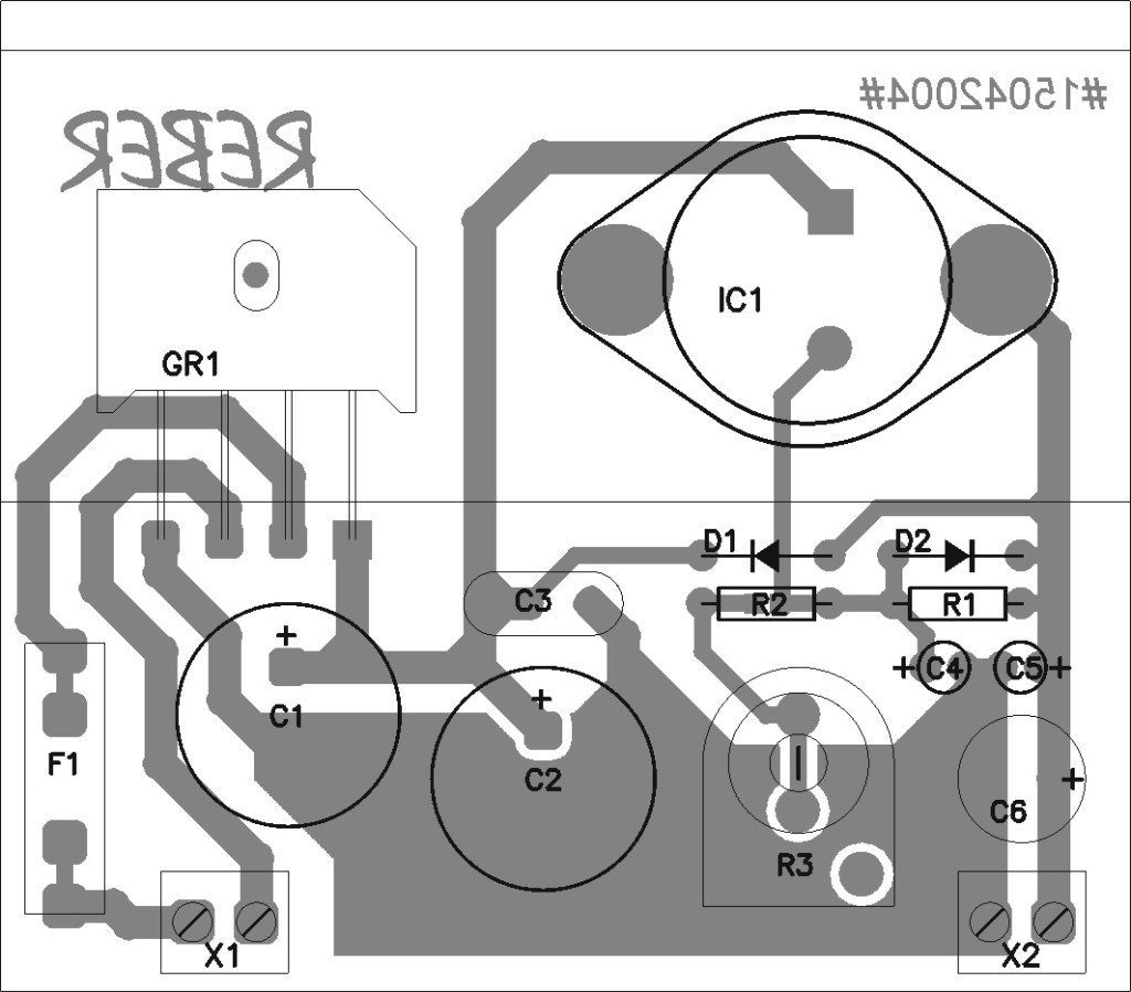
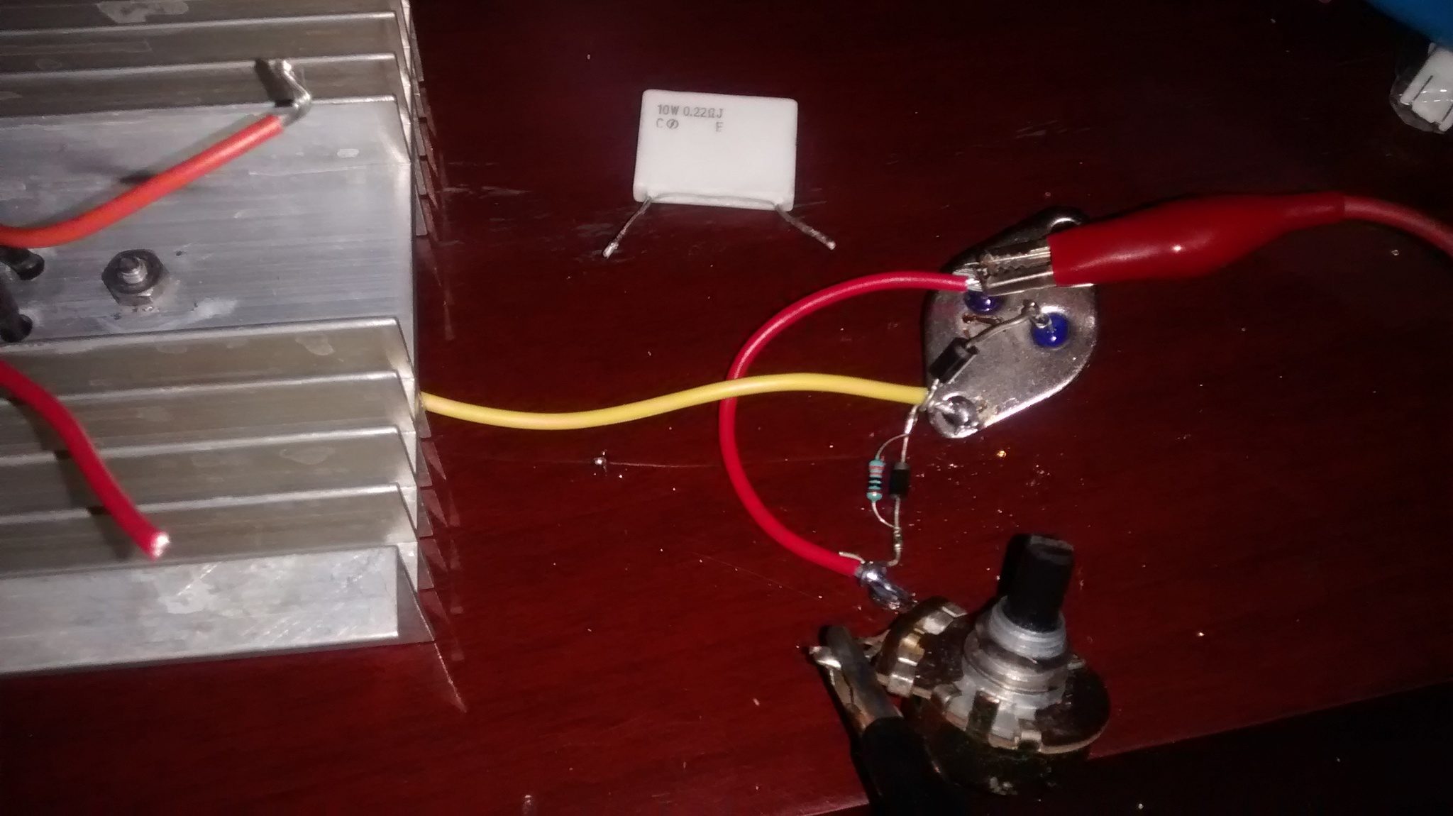
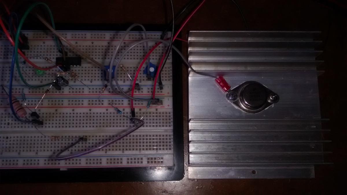
Bom Vou mostrar os meus testes: A PCI: O diagrama: Nao consigo regurar o LM de jeito nenhum... ai muito bravo ja estava, resolvi fazer a fonte do faller de sem os TIPs á claro! E funcionou perfeitamente! Variava e tudo mais! E eu contente pra caramba foi testar a corrente e coloquei um resistor de 0,22 ohms na saida! ADIVINHEM! A saida zerou! Mesmo com dissipador e tudo! Me acalmei, esperei um tempo...(nao sei porque) e mesmo assim não ligou de jeito nenhum! OK peguei outro LM e fiz exatamente a mesmo ligação e coloquei uma lampada de led de carro para simular, variava normal, e voltei ao resisitor de 0,22... alem de ter ido OUTRO LM pro saco, meu potenciômetro também foi! O LM no dissipador apos ter queimado e o outro sem o dissipador! Pode ser LM falsos? pois foram comprados no ALIEXPRESS... 5 por R$30,00 Por favor alguém pode me ajudar!? @faller @Tomazelli @Isadora Ferraz @Bcpetronzio
-
Boa Noite a todos! Depois de quase um ano vou resgatar o topico, Montei o carregador....porém ele nao funcionou.... (Montei na placa com dissipador de calor antes que me fuzilen...kkk) no trimpot eu nao consigo variar, a tensão que entra no LM338 é a mesma que sai.... nao importa o que eu faco! o que poderas ser? o LM com defeito? Logo mais estarei postando a PCI
-
Boa Noite! Estou voltando a programação e resolvi deixar de lado os PICs e partir para o Arduino, por ser mais fácil as declarações bit a bit dos registradores, e novamente quero montar um relogio digital com o DS3231 e um LCD 16x2. Apos montar isso vou incrementando cada vez mais, mas por agora o desafio já é grande, pois a minha biblioteca do RTC nao quer funcionar , o arduino nao reconhece. A parte do LCD funcionar ja consegui: Coloquei o contador só para o LCD não ficar parado... Depois colocar 3 botões: Set, Incrementa ( + ) ,Decrementa ( - ) Aguardo! Obrigado!
-
PC novo
Bruno R Ruinho respondeu ao tópico de Bruno R Ruinho em Montagem e upgrade de computadores de mesa
Obrigado pelas dicas da fonte e memória, vou dar uma pesquisada no Kabum, e posto aqui. O processador seria um i5 mas vai ser bem mais para frente, a placa de vídeo não sei ainda, seria só para rodar o Sketchup não preciso de muito. Obrigado a todos!! -
Boa Tarde a Todos! Estou querendo comprar um PC novo mas como o orçamento esta apertado, vou comprar por partes; O gabinete já tenho da C3 Tech, agora partiria para a fonte: Fonte ATX 3R System Iceage IA500HP80 500W - Bivolt ou Fonte CaseMall ATX 500W MP-0500A80 Supreme Power + 2x Gravador Interno ASUS DVD 24x Black DRW-24F1MT/BLK/B/AS 90DD01V0-B3B00 + fan de 120mm para o gabinete FUTURAMENTE: Placa mãe Gigabyte p/ Intel GA-H81M-S3PH LGA 1150 Box Memória Corsair 8GB 1600MHz DDR3 PC12800 CMV8GX3M1A1600C11 HD Interno WD 1TB SATA 7200RPM Edição Blue - WD10EZEX-00BN5A0 SSD Sandisk PLUS 2.5´ SATA 3.0 (6 Gb/s) 120GB Leituras: 520MB/s - SDSSDA-120G-G25
-
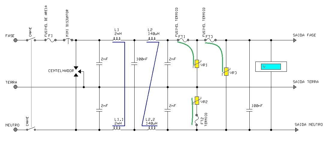
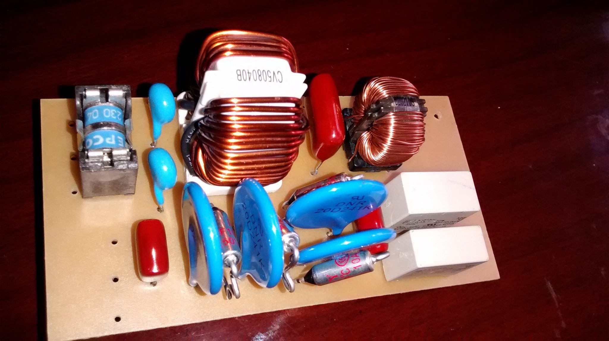
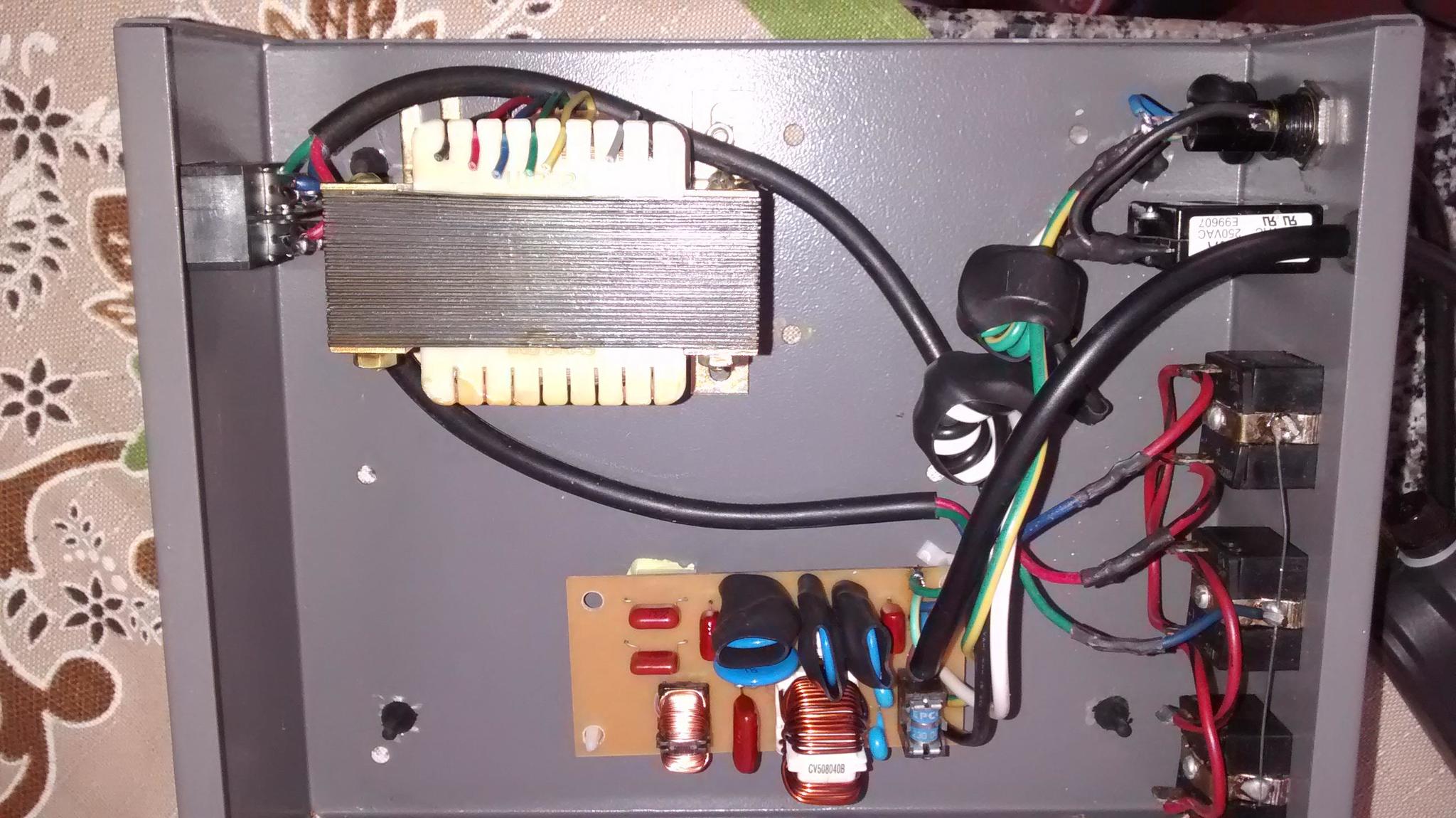
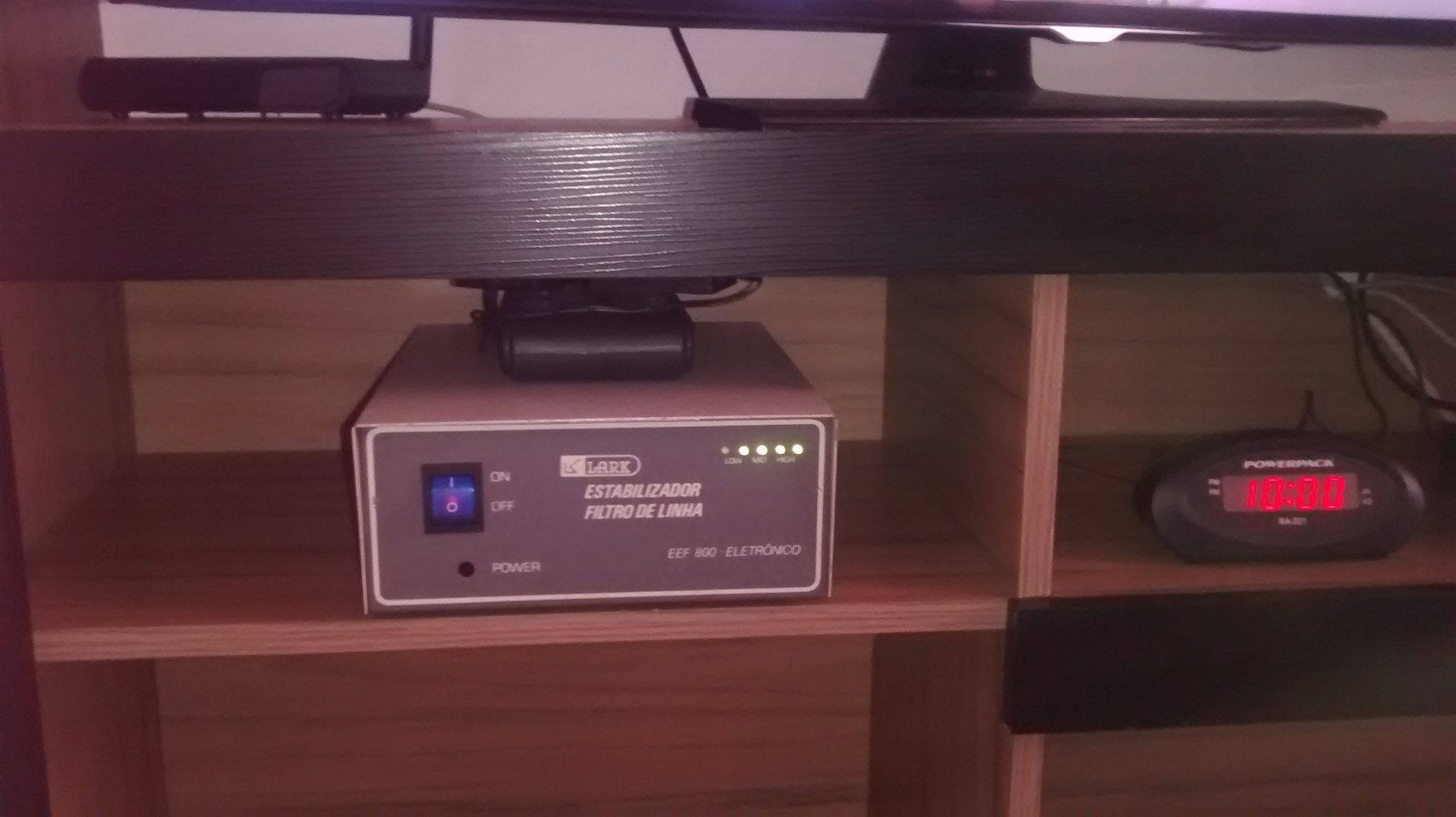
Decidi montar meu 1° filtro de linha, com as experiencias, projetos de muitos membros, visualizando os grandes fabricantes, os de “fundo de quintal” e pegando o que ha de melhor em todos. Fiz a mesma ideia de nosso amigo Faller peguei um gabinete de estabilizador desativado, sem toda parte interma (mesmo querendo ,mais que tudo utilizar, o estabilizador em estado solido), um ótimo filtro de linha para minha sala. Características: - Dispositivo de simples execução; - 3 Tomadas na parte traseira, obedecendo a chave frontal; - 6 Tomadas na parte superior do equipamento, que serve para ligar o Modem, Roteador e Relogio que irão ficar sempre alimentados, obedecemdo a propria chave; - No painel frontal uma chave liga desliga que ativa as 3 tomadas do painel traseiro, ao sair de casa para trabalhar, desliga os equipamentos nessas tomadas; - Indicação frontal com 5 led´s, leds bicolor – verde e verelho (verde sempre OK); Led 01: Quando vermelho indica fusível principal aberto (de areia); Led 02: Quando vermelho disjuntor desarmado; Led 03: Quando vermelho fusivel termico entre F-T aberto; Led 04: Quando vermelho fusivel termico entre F-N aberto; Led 05: Vazio (aguardando alguma ideia). - Filtragem de ruídos de 4ª ordem, com bobinas toroidais e capacitores apropriados; - Frequência de corte do filtro passa-baixas, menor ou igual a 5kHz e atenuação maior que 45 dB a 100 kHz; - Proteção entre fase-terra, com varistores de 20 mm, com fusíveis térmicos de proteção, normalmente 100ºC; - Proteção principal, entre fase-neutro, com dois varistores em paralelo de 20mm e dois fusíveis térmicos de 100ºC acoplado; - Varistores com tensão de ruptura de 150 Volts rms minimizando a possibilidade da tensão de trabalho nominal, mesmo que elevada mas dentro da tolerância, ativar a proteção; - Proteção de extrema capacidade com centelhador tripolar a gás, para segurar algum surto de tensão tipo um raio caindo na rede. Obs: O varistor VR2, que interliga Neutro e Terra, foi substituído por um com a menor tensão de serviço possível, em torno de 15 a 30 Volts. Porém terá que ter certeza da polarização da entrada, pois se a mesma for invertida, provocará um curto rompendo o fusível, e possivelmente destruindo o varistor. MOTIVOS PARA UTILIZAR A PROTEÇÃO/FILTRO Surtos de Tensão Os surtos de tensão podem ter duas origens distintas: interna ou externa. Os surtos de tensão internos, geralmente, têm as seguintes causas: • Comutação de cargas indutivas; • Faiscamento (“Flashover”); • Interferências causadas por acoplamentos capacitivos ou indutivos com outros componentes (por exemplo, comutação de banco de capacitores para correção do fator de potência); • Descargas eletrostáticas (ESD). Já as causas externas para surtos são: • Acoplamento elétrico a potenciais mais altos; • Comutações na rede de alimentação; • Descargas atmosféricas; • Interferência indutiva (se um curto-circuito ocorrer numa linha de força, particularmente onde o neutro é aterrado, tensões muito altas podem ser induzidas em linhas adjacentes); • Interferência causada por campo magnético interno (provocada, por exemplo, pela queda de um raio em área próxima ao equipamento). COMPONENTES DE PROTEÇÃO Varistores Os varistores são resistências não lineares dependentes da tensão, com características logarítmicas definidas de tensão e corrente. A elevação de tensão reduz a resistência e, consequentemente, aumenta a corrente. Na ausência de sobretensão, a resistência do varistor é bastante elevada, como um circuito aberto. Entretanto, na ocorrência de um transiente, sua resistência cai drasticamente, mantendo a tensão entre os terminais em valores baixos. O “excesso” de tensão é dissipado em forma de calor. Instalação O varistor deve ser instalado em paralelo com a carga a ser protegida. Para redes monofásicas o processo é muito simples conforme utilizamos em nosso circuito, tanto a sobretensão entre fases, como a sobretensão entre fase e terra / neutro devem ser contempladas. Centelhadores a Gás São dispositivos formados por dois ou três eletrodos internalizados em um tubo de cerâmica ou vidro e separados por uma distância pré-determinada. Os centelhadores podem conduzir correntes de fuga, dependendo da tecnologia que o fabricante usa na manufatura do invólucro. Além do mais, a tensão disruptiva característica de um centelhador depende do meio ambiente no interior dos eletrodos. Se o interior do invólucro é preenchido com gás, a tensão disruptiva é função de sua pressão. Se o centelhador é do tipo aberto (ar), a tensão disruptiva pode variar com a umidade e com grau de poluentes no local de instalação. Os centelhadores a gás consistem de um tubo contendo gás inerte, o qual sob condições normais de operação apresenta características de um circuito aberto. Contudo, na ocorrência de um transiente, o gás se ioniza permitindo a passagem de corrente. O gás permanece ionizado até que a corrente caia a um valor denominado “holding current” especificado para cada tipo de centelhador. Devido à sua característica de operação, os centelhadores são extensivamente usados nas redes telefônicas para proteção contra descargas atmosféricas. Eles não necessitam de manutenções e possuem um tempo de vida útil em torno de 30 anos. Se comparados a outros dispositivos, os centelhadores são um tanto insensíveis, já que são necessários aproximadamente 700 V para provocar a ionização do gás interno do tubo. D epois de todas as caracteristicas segue o esquemático que pode ser visto ai abaixo: Detalhe dos fusiveis termicos com ponto de fusão em 100º C, deve-se ter cuidado em soldar seus terminais, senão pode danificalos no processo de soldagem por super-aquecimento. Diagrama e placa de indicação de fusivel queimado Uma visão da placa que sustenta a proteção e filtro, já com todas as peças montadas. Note que cada fusível térmico é acoplado ao seu varistor com pasta térmica para melhorar o acoplamento térmico entre ambos. E todos com termo retratil. Note o processo adotado para manter os terminais dos fusíveis térmicos longos, para dissipar o calor na hora da soldagem (mesmo assim é recomendado usar um alicate pinçando esse terminal, para não arriscar a queima do componente no processo de soldagem.) OBRIGADO A TODOS! CRITICAS E SUGESTÕES SÓ POSTAR!
-
Por que adotar proteção adicional na linha telefônica e de TV a cabo?
Bruno R Ruinho respondeu ao tópico de faller em Fontes e energia
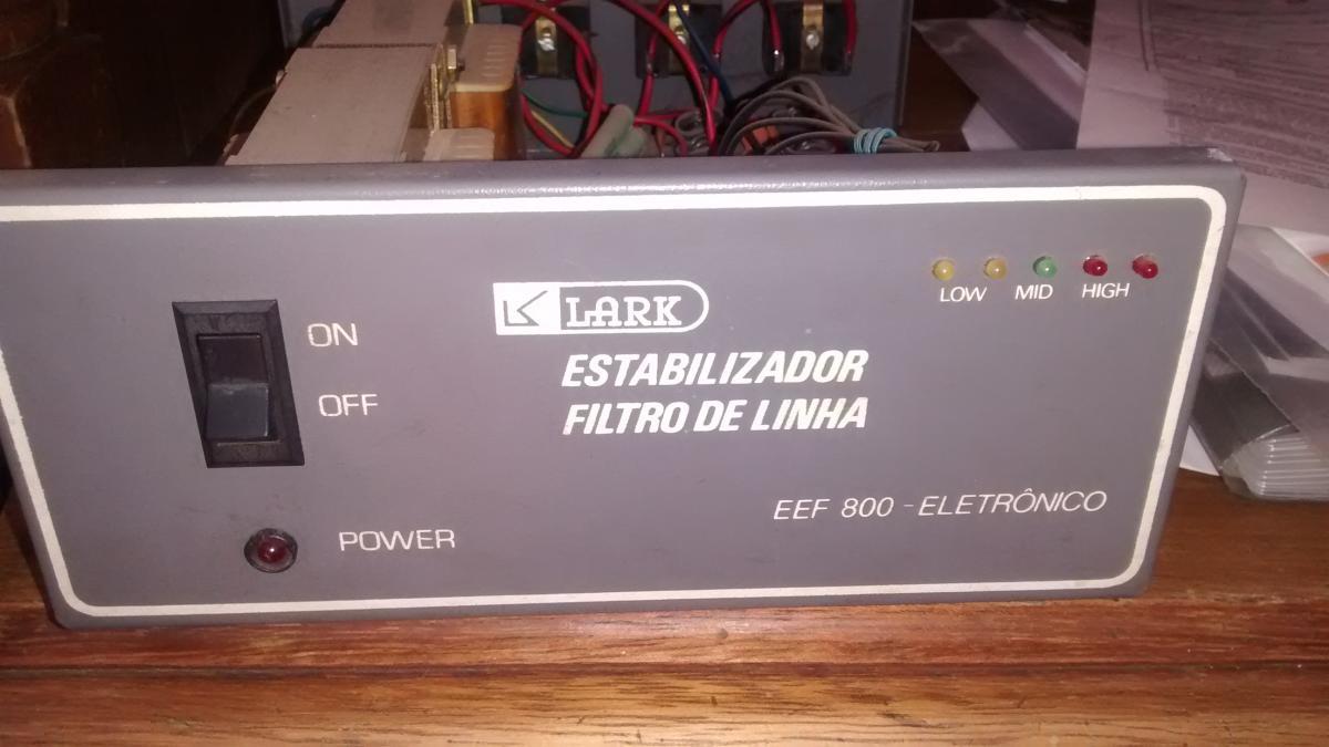
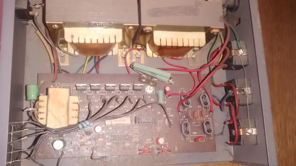
Bom Dia a Todos! Estava querendo melhorar um estabilizador que tenho aqui faz anos, parado, resolvi abrir para utilizar somente a carcaça, mas me deparei com isso>>> Tudo parece ser um estabilizador eletrônico, pois nao possui reles, agora vem a pergunta: Este estabilizador é melhor que os outros ou tem um diferencial consideravel? Vou utilizar na sala para TV, relogio, modem, roteador, DVD. Ele vai ser util da seguite maneira somente como chave geral, quando eu sair de casa para trabalhar desligo tudo (somente o modem ficara ligado 24hras) Posso melhorar a proteção dele? Aguardo e Obrigado!
-
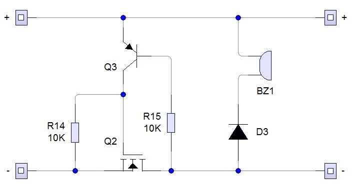
@Tomazelli Obrigado pelo esclarecimento, ja estou em processo de montagem, em breve vou postar aqui, vou fazer o circuito de proteção e retirar aquele diodo.!
-
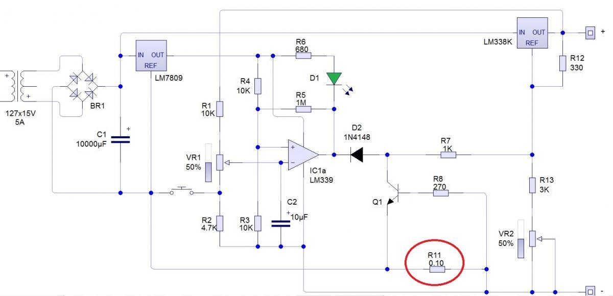
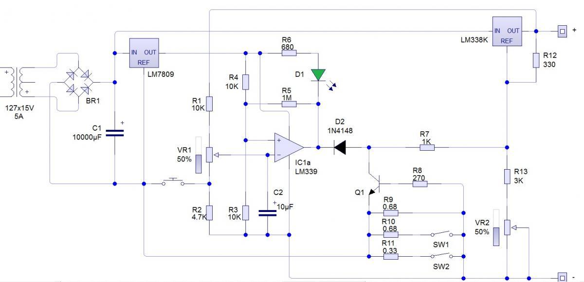
Qual parte da potencia que você se refere a fonte do faller? pois tem 2 TIP 147 em paralelo e depois o LM338, seria ate os 2 TIPs? Re-desenhei seu circuito para entender melhor: Só esta faltando essa parte que voce comentou (da parte de potencia) esta tudo ok? Obrigado!
-
Eu estava quase me encontrando, agora depois dessa eu me perdi totalmente! Anteriormente este circuito não estava atendendo o proposito? Ou ele esta sinalizando alguma coisa errada ?
-
ok, esclareceu bem essa parte, no circuito em verde voce omitiu o resistor que mede a corrente (pois ficou aberto entre o GND e GND1)? Muito Obrigado pelas respostas!
-
No seu circuito a carga termina verificando a correte correto? Bom nos 2 casos a bateria estará carregada, tanto o circuito verificando a corrente como verificado a tensão? Estou no processo de desenhar a placa ainda, mas logo logo ja posto os circuitos! Obrigado!
-
Vou desenhar na própria PCB e corroer, sem medo de ser feliz, só um detalhe, o GND do lm339 tem que ser ligado antes do resistor de 0,11 ou não faz diferença? e o proprio lm339 pode ser substtuido por um 741 ou 311 ? Obrigado!
-
Boa essa.. Bom Isadora, essa parte da explicacao nao vou conseguir te responder exato pois o circuito foi desenvolvido pelo @faller, pelo que entendi quando a saida estiver alta ela vai reduzir um pouco a tensão de saida para que a bateria permaneca em flutuacao,(foi o que eu deduzi). Mas somente ele para esclarecer... Estou terminando meu curso e este sera o trabalho de conclusao, por isso estou desesperado... Se tiver algo em mente poderia postar tambem? Obrigado e Aguardo!
-
@Isadora Ferraz @_xyko_ @faller @mroberto98 @albert_emule @Bcpetronzio
-
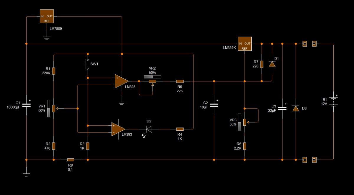
Bom Dia a todos! Montei o carregador abaixo, porém deu um pequeno problema: Alterei a parte das chaves e o resistor para 4,5A (em vermelho) pelo calculo deu o valor 0,10 esta correto? Quando vou regular o trimpot do LM339K ele vai ate 13,8v quanto vou subir para 13,9,,14 ele cai para 11,6 somente se voltar o trimpot ele volta para 13,8 o que pode estar acontecendo? a tensão de entrada esta em 19v apos o capacitor O LM338K esta em um bom dissipador de calor. Aguardo
-
Fiz a alteração que o @faller comentou no post antigo, quero carregar uma bateria de 50Ah portanto 5A esta otimo, Em vez do LM339 Amp-OP nao teria problema de utilizar um 741 de "uso geral" ? Calculo do Rlimite deram esses valores: Para 4.5A meu resistor e 0.15ohms Potencia para 4.5A = 3.2w Vou colocar um de 5W para garantir, e não esquecendo a proteção do @Tomazelli caso inverta a polaridade da bateria ou as garras se encostatem. Obrigado a todos!
-
Alguém?
-
@Tomazelli posso resgatar seu post? Muito bom mas eu li e re-li varias vezes, estou querendo montar um carregador de baterias faz um tempo, agora que meus LM338K chegaram eu não tenho mais desculpas do porque nao monta-lo. Você usa esse carregador ate hoje ou montou um mais poderoso? estava pesquisando aqui no forum mesmo e achei um do nosso amigo @faller :http://forum.clubedohardware.com.br/forums/topic/887697-resolvido-lm-301/page-2 como também sempre prezo pela simplicidade este parece um bom circuito. Gostaria de montar um carregador simples de 5A com o desligamento automático ou flutuação (que pelo vi os 2 circuitos atendem). Aguardo a ajuda de todos! Obrigado!
-
Bom Dia! Varistor fisicamente ele é parecido com um capacitor ceramico,na foto do site que voce mencionou não aparece nenhum varistor. Varistor é um "resistor" é praticamente um resistor variável (em função da tensão). Assim: Você determina uma tensão de trabalho ex: 130v a partir dessa tensão ele vai alterar sua resistência interna, se colocar ele na tomada em torno de 120v ele ficará normal, se começar a aproximar dos 130v a resistência cai e quando chega aos 130 ele entra em curto e assim carbonizando ele e queimando o fusivel e todo o conjunto proteje seu circuito. Para medir coloque na escala de resistência o valor tem que ser infinito pois você não estará aplicando nenhuma tensão


Sobre o Clube do Hardware
No ar desde 1996, o Clube do Hardware é uma das maiores, mais antigas e mais respeitadas comunidades sobre tecnologia do Brasil. Leia mais
Direitos autorais
Não permitimos a cópia ou reprodução do conteúdo do nosso site, fórum, newsletters e redes sociais, mesmo citando-se a fonte. Leia mais